This is an old revision of the document!

IH: Oiling & Lubrication
Engine Oil Routes


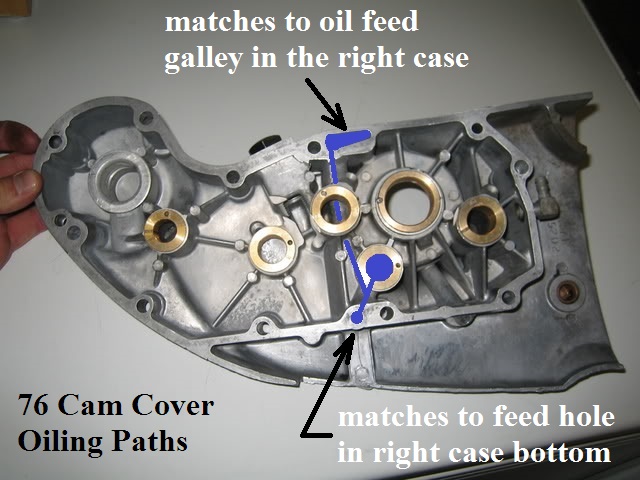
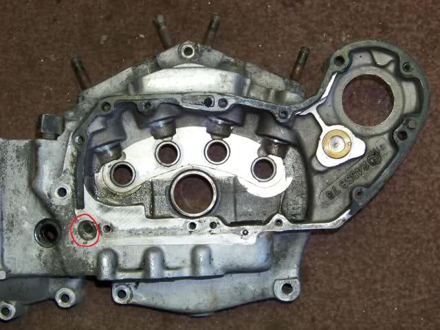
Right Crankcase Feed Galley
The lifter oil feed galley is a hole located along the top of the case between both intake tappets.
- The feed galley is responsible for carrying oil to the rocker boxes.
- It gets it's oil from the oil pump by routed holes in the cam cover.
- A hole is internally routed from the top to the bottom of the cover with a hole exiting in a corresponding hole in the case.
- The cam cover gets it's oil from the oil pump via intersecting holes between the bottom of the case and the cover.
- Feed oil is routed inside the cover but not to the gearcase.
- The hole in the middle of the case at the top intersects into the internal oil feed galley to the rocker box oil lines.
- Pressurized oil travels up the oil lines to the rocker arms.
- This is the end point of static oil pump pressure to the top end.
Gravity oil drains from the boxes thru the head / cylinder drains into the crankcase and down the pushrod tubes into the cam chest.
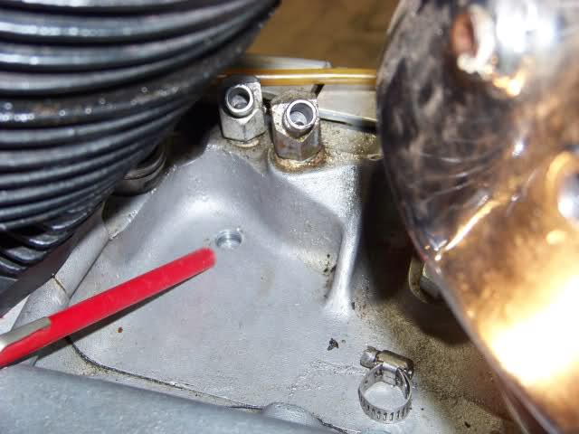
| Oil feed on 76 XLCH 3) |
 |
Top End Oiling
Rocker Arm / Valve Oiling


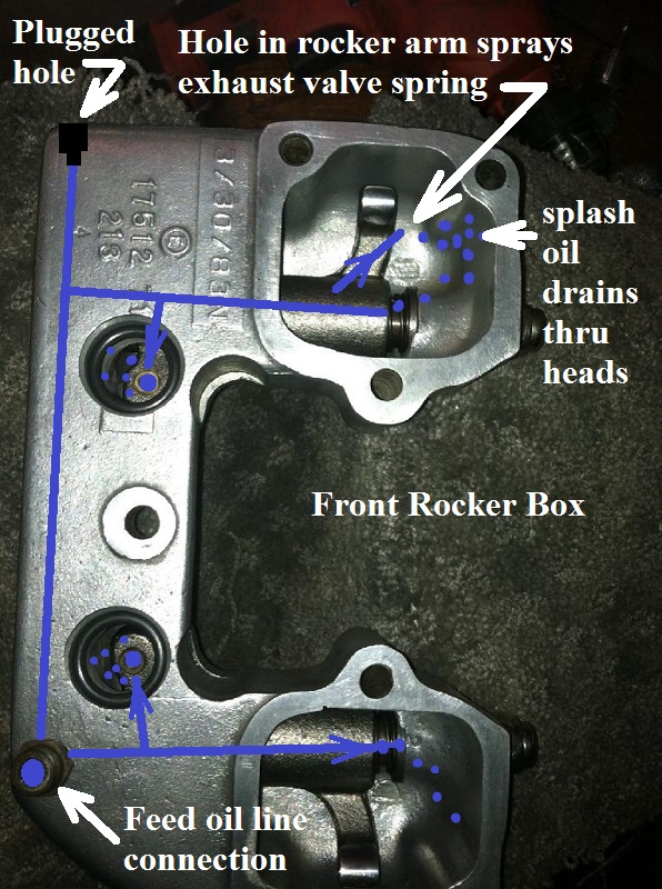
Rocker Box Oiling
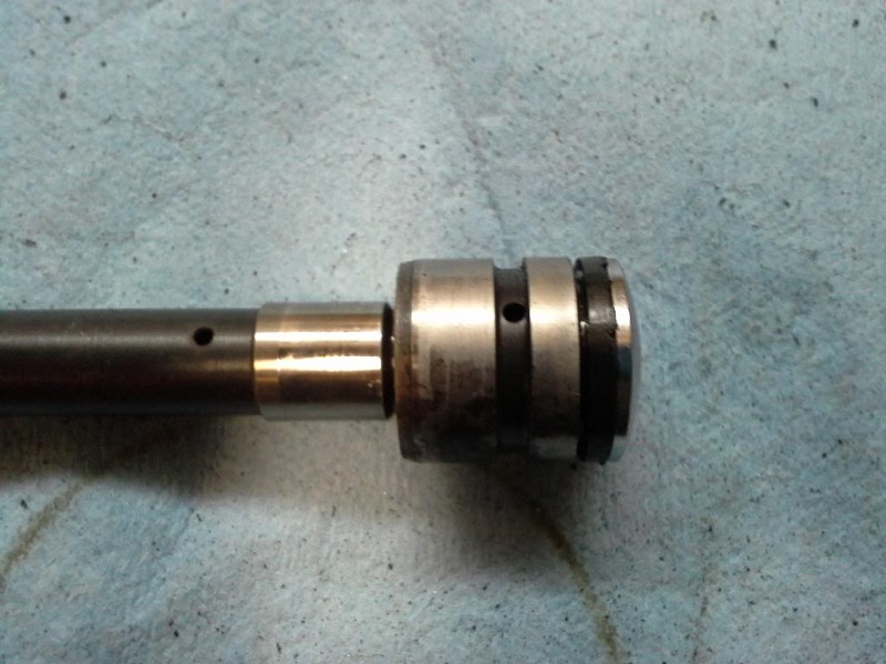
Oil travels in a passage between the two rocker arm shafts (big end).
The oil line comes from underneath into one shaft bore on the pushrod side in each rocker box.
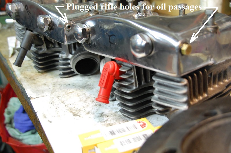
There is a rifle drilled hole between the rocker arm shafts in each box that connects the two for oil passage.
Each hole is plugged off on the outside of the box.
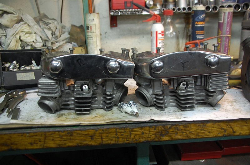
| Front rocker box oiling. | Rocker Boxes on 69 model. 7) | |
 |  |  |
Bottom End Oiling
Pinion shaft and Crank Pin
Cam Cover Bushings
Cam Cover \ Gasket
| 76 cam cover oiling paths. 8) |
 |
Oil tank vent fitting:
Starting in 1967 (XLH) and 1970 (XLCH), the oil tank vent line was routed into the rear side of the cam cover.
A 1/4“ rubber hose is routed from the oil tank to the 90° (1/8” NPT) fitting at the cover.
The line mostly vents oil tank air back to the gearcase mixed with an oil mist.
If the vent line is kinked or blocked, pressure will back up in the tank and pop the cap and splash oil everywhere.
| Oil tank vent fitting on 1973 XLH 9) |
 |
Head Drainage
| Head drains on 83 XLX 10) |
 |
Case Oiling and Drainage
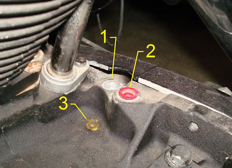
Engine Oil Fittings / Locations
- 1957-1966 XLH and 1958-1969 XLCH:
- Oil feed from the tank is on the top of the case behind the rear cylinder (rear fitting).
- Oil return to the tank is on the top of the case behind the rear cylinder (front fitting).
Used 3/16“ steel tubing, bare ended, with rubber seal compression fittings.- 63525-50 NPT to tube connector fitting (both ends).
- 63529-57 Rubber sleeve seal for 3/16” pipe (both ends).
- 63527-50 Oil line nut (both ends).
- 63507-56A Steel oil return line.
- Vent line from the oil tank is on the top of the case behind the rear cylinder (lowest and smallest, 1/4“ hose fitting).
- The primary / transmission vents thru the motor internally via the oil transfer valve.
- 1967-1976 XLH and 1970-1976 XLCH:
- Oil feed from the tank is on the rear of the oil pump (3/8” hose fitting).
- Oil return to the tank is on the top of the case behind the rear cylinder (3/8“ hose fitting).
- Vent line from the oil tank is on the rear of the cam cover (1/4” hose 90° fitting).
- The primary / transmission vents thru the motor internally via the oil transfer valve.
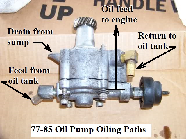
- 1977-1985 (all models):
- Oil feed from the tank is on the lower rear of the oil pump (3/8“ hose fitting).
- Oil return to the tank is on the upper front of the oil pump (3/8” hose fitting).
- Vent line from the oil tank is on the rear of the cam cover (1/4“ hose 90° fitting).
- The primary / transmission is vented to atmosphere from the top of the transmission near the rear motor mount just in front of the solenoid (1/4” hose fitting).
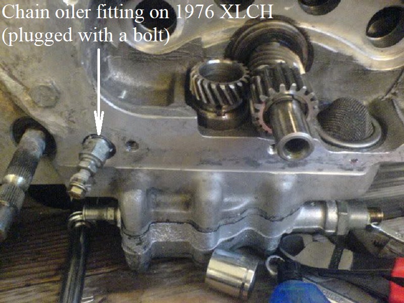
Rear Chain Oiler (57-76)
The chain oiler is a designed leak to keep the chain from rusting up. There is a factory adjusting screw to control the amount of oil it gives.
Return oil is tapped into to provide a drip for the chain. Due to it's nature, there will always be an oil leak from it.
If you don't want the leak, you can try and tighten the adjusting screw.
But chances are the screw or fitting itself has previously been tightened too much leading to an eternal leak.
Most will either plug the oiler fitting with a bolt / screw or remove the oiler fitting and install an 1/8“x27 NPT plug there and oil the chain by other means.
You can also run alternately run a hose from the crankcase breather pipe back to oil the chain (mostly oil mist at best).
However, it is far better to use a good quality chain wax. It won't fling off all over the bike or rear tire. 14)
Location:
The chain oiler fitting is either located behind the sprocket cover or at the oil tank respectively of year model and sometimes which tank you use.
- 1954-1966 KH, XL and XLH used a (63607-53) 2-way (2 NPT) x SAE threaded regulating fitting.
- 1958-1969 XLCH used a (63601-54) 2-way (1-NPT) x (SAE) x 1/4” hose bibb regulating fitting mounted to the oil tank.
- (63611-53), chain oiler upper hose bracket mounts to the top of the case under the (R) motor mount bolt.
- (63612-53), chain oiler lower hose bracket mounts to the rear motor mount front right bolt to the case.
- 1967-E1972 XLH and 1970-E1972 XLCH used a (63595-67) hex body flared connection regulating fitting with a mounting tab to the top of the motor behind the rear sprocket.
- L1972-1976 XLH and XLCH used a (63595-72) updated hex body flared connection regulating fitting with a mounting tab to the top of the motor behind the rear sprocket.
Adjustment: 15) 16)
Inspect the chain at regular service intervals (1000 miles) to see if it is getting enough oil or too much oil.
To adjust the amount of oil given, loosen the lock nut (if used) on the fitting and turn the screw outward for more oil or inward for less oil.
Only turn the screw a little at a time and tighten the locknut (if used) on the screw when done.
Cleaning: 17) 18)
Debris and gummed up oil accumulated in the oil supply will gather at the orifice and slow/stop the flow of oil from time to time.
So the tubing should be blown out periodically to help prevent this.
Back out the locknut on the screw (if used).
Turn the adjusting screw in until it bottoms on it's seat while counting the number of turns you made to get there.
Remove the screw and blow out the orifice with compressed air.
Reinstall the screw until it bottoms out and back it out the number of turns counted earlier and lock it in place with the locknut (if used).
It should be set to allow 2-3 drops of oil per minute (app 1/4 turn on 1957-1968 models and app 3/4 turn on 1969-1976 models).
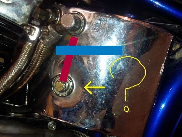
Below is a L1962-1965 XLCH “horseshoe” oil tank with an explanation of how the chain oiler gets it's oil.
The blue line is the oil level. The red line is a tube inside the tank. The bottom of that tube feeds the lower (chain oiler) fitting.
The top of the tube is open and above the oil level. So, nothing drains out of the bottom fitting if you open it.
Note the open top of red tube is directly below the return fitting.
When the bike is running, return oil spills into the red tube to supply the chain oiler fitting installed in the lower port.
This feeds chain only when the engine is running and doesn't leak when the bike is shut off.
 19)
19)

Splash
Oil Pump Scavenge
See also the IH Oil Pump section of the Sportsterpedia.
'57-'76 Cases
An engine sitting for a while not running can “sit-sump” oil into the primary.
Read more on Sit Sumping in the Sportsterpedia.
On engine start up the excess oil in the primary should be transferred back into the engine (but not all at once).
In the event oil from the oil pump seeps into the crankcase high enough to spill over into the primary, on startup, that oil is sent into the crankcase by way of the transfer valve.
On piston downstroke, positive crankcase pressure closes the transfer valve and seals a small hole preventing flow into the primary.
On piston upstroke, vacuum in the crankcase opens the transfer valve and sends a burst of oil/air into the crankcase.
Read more about the Transfer Valve in the Sportsterpedia.
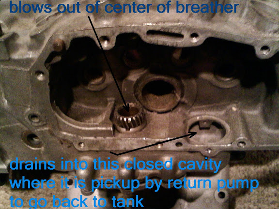
The pics below show the oil flow from the flywheel cavity to the return pump.
In stock configuration, most all used oil ends up in the flywheel cavity.
The small amount that gets supplied to the upper pushrod ball/socket goes into the gearcase.
While the splash oil to the exhaust valves enters the crankcase through the head drains.
The two crankcase halves together form the oil scavenging slot where oil is sent out of the sump to the oil pump.
The open slot receives oil by splash from the wheels and oil is forced into and thru the slot by way of positive crankcase pressure (downstroke of the pistons).
The scavenge slot is blocked off on the left side by the crankcase wall.

Oil is pushed by the pistons thru the slot into the right case where it gathers in the oil trap at the oil pump mount.
Oil is picked up through the windows in the breather gear and slung into the gearcase and drained thru a strainer into the oil pump scavenge gears and sent back to the oil tank.
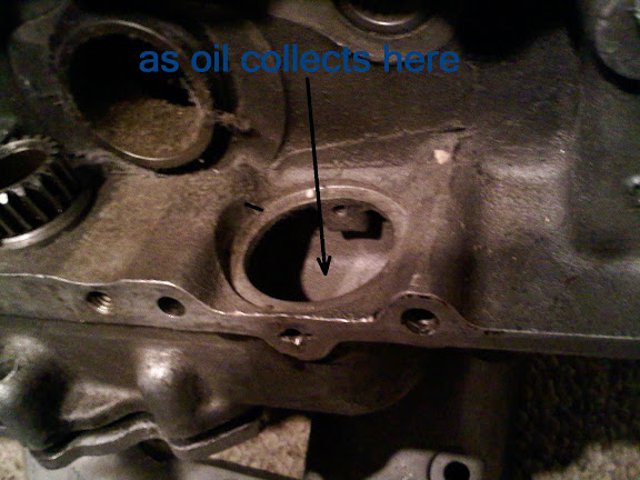
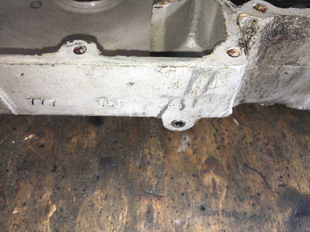
'77 and Later Cases
The “drain plug” on the bottom of the case is simply a threaded plug that caps the oil scavenging passageway. 30)
However, it's not really a drain but rather a plug in a machined oil passage.
The MoCo drilled from the bottom of the case to the horizontal oil passage in the gearcase.
This connects the crankcase sump oil to the scavenge port of the oil pump and the hole is plugged on the bottom.
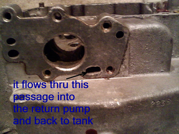
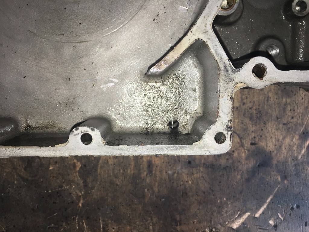
From inside the case with the plug removed from the scavenge passage;
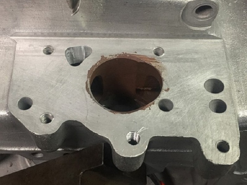
In the second pic below, you can see that the threads, from the tap, have been machined farther up into this hole.
This is the oil passage from the sump to the scavenge pump.
Oil from cylinder drains, crankpin, pushrods and cam chest that collects in the sump is fed to the pump by crankcase pressure and pump suction through this hole.
As you can see, even if you remove the plug, you still cannot drain the entire sump due to the mounting bosses (ribs) for the cover bolts.
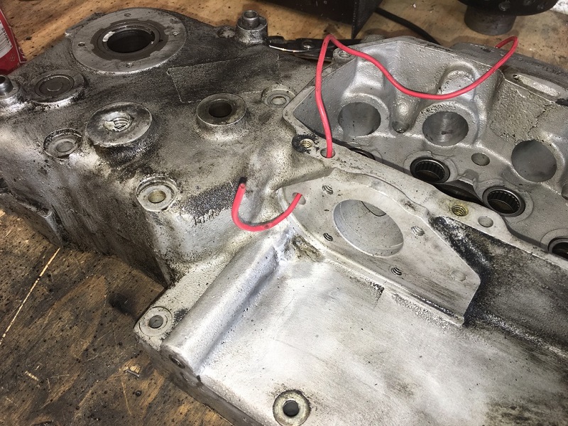
In the third pic below, you can see where they drilled the case from the side where the cam cover goes and the bottom where the oil pump return hole goes.
The hole drilled from the cam cover side doesn't go anywhere. It dead ends into the cam cover flange.
Caution: If you use silicone on your gaskets, the silicone could easily enter the oil passage and enter your pump.
| Scavenge passage on 77 engines 31) | ||
 |  |  |
Gravity