Table of Contents
This is an old revision of the document!

REF: Carburetor, Intake Manifold & Exhaust
Keihin Carb Upgrades - Butterfly and CV Types
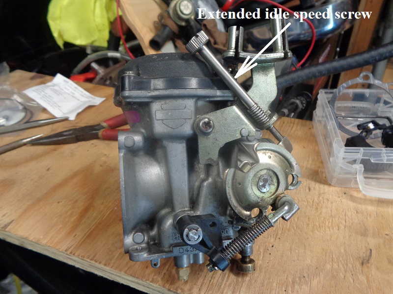
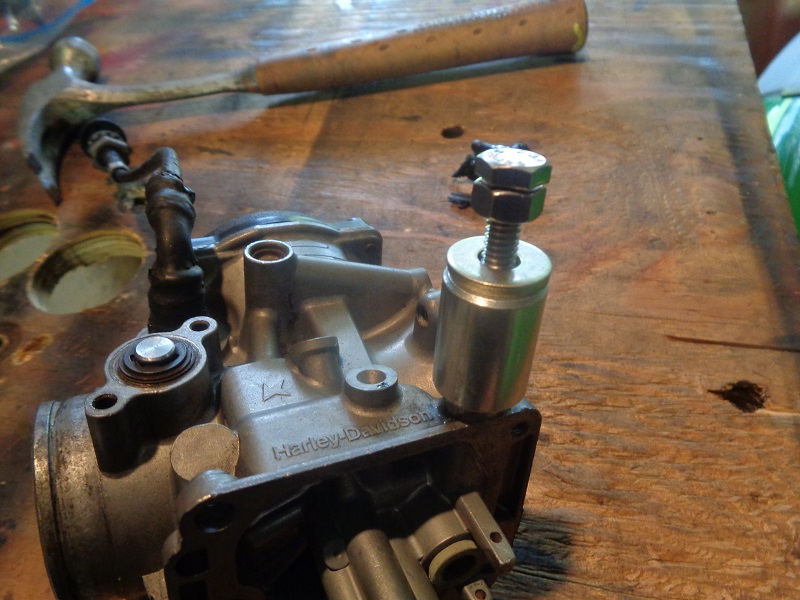
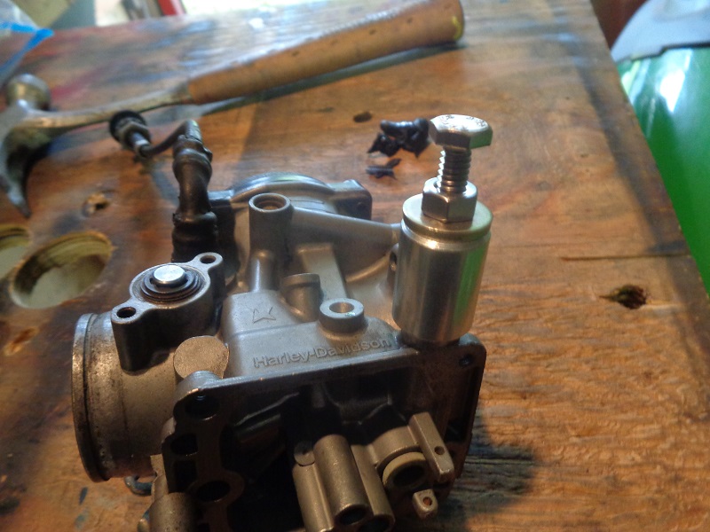
Extended Idle Speed Screw
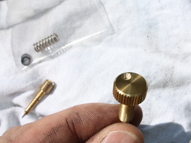
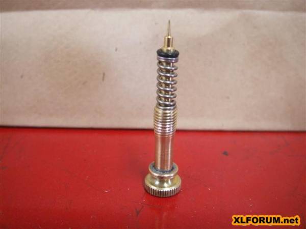
Below is a CVP stainless steel idle speed screw for Harley CV and Keihin butterfly style carburetors.
With the extended thumbscrew, idle speed can be adjusted by hand.
It's also slotted for a large tipped screwdriver if longer reach is still needed.
It also includes a stainless steel spring.
For use on all Harley CV40 and Keihin butterfly style carbs 1981-2006. 1)
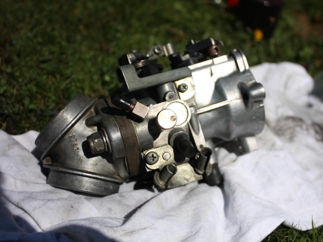
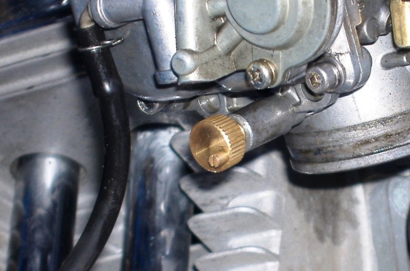
| Long idle speed screw on a Keihin CV. 2) |
 |
Aftermarket Idle Mixture Screws and Mods
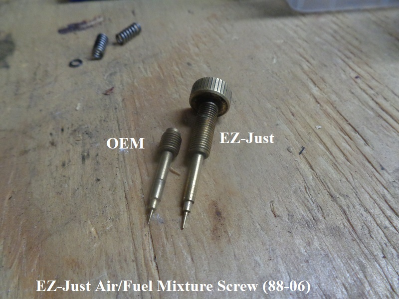
EZ-Just Mixture Screws
The EZ-Just mixture screw (for L76-87 or 88-06 models) 3) ) can be purchased with an extended screw head for hand tuning.
You can buy packing from CVP also in case yours has been damaged or is not functioning properly.
But, check your local regulations before changing this out to an aftermarket part.
You can also find, buy or barter for used parts.
(“Please note: it is a violation of federal law to tamper with or disable any emission or noise control device. That is your PSA for the day”). 4)
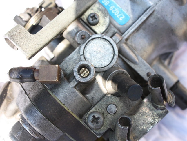
If you still have the factory plug over the mixture screw, you'll need to drill it out to access the screw.
To keep from drilling too far into the plug, you can use some electrical tape around the drill bit to mark the depth to drill.
Then pry the plug out using a pick or you could twist a small sheet metal screw into the hole to pull the plug out.
With the plug removed clean the area around the mixture screw so no metal fragments remain.
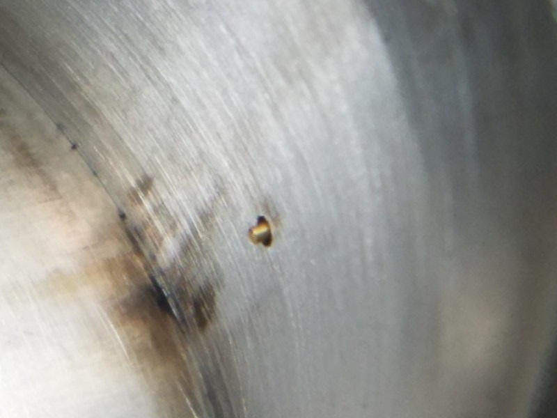
 5) Circled area is where you drill out the plug.
 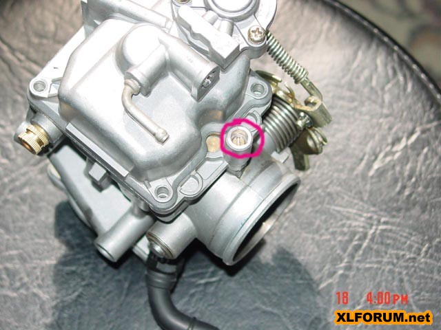 6)
6)
The EZ-Just mixture screw must be threaded in completely (lightly seated) prior to backing out and making final adjustments.
Typically between 10-12 full rotations of the screw to seat.
If you can see more than 1-2 threads after seating the screw, the screw is not screwed in completely.
This could result in the screw falling out during operation.
If you have trouble fully threading the EZ-Just, this indicates the inside threads of the carburetor need cleaning or have a damaged thread inside.
Working the screw in/out with light machine oil (3-In-1 or other) will often help work past any carbon build up inside the carburetor threads.
The packing for the EZ-Just is the same as OEM:
screw, spring, washer, O-ring.
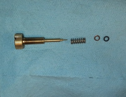 7)
7)
L76-87

88-06
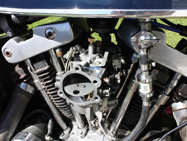
This screw is billed as “Easily tune and adjust your idle mixture without burning your hands or fumbling with a screwdriver.” 11)
This is not entirely true as you have to get your hand between the exhaust and air cleaner.
Tuning and installation tips here at CV Performance.com.
The carburetor will need to be removed from the manifold so refer to your factory shop manual for this procedure.
With the carburetor removed, place upside down on a sturdy work surface.
The float bowl doesn't need to be removed unless you have to issues removing the factory packing and/or need to blow out the passageway.
If you take off the bowl, be sure to check the float setting before reinstalling the bowl.
| EZ-Just Screw in it's 'lightly seated' position. 12) | |
 |  |


EZ-Just Thumbscrew Mods
Several mods to the thumbscrew have been done to make counting turns while turning the screw easier.
| The aftermarket thumb screw head doesn't a slot for a screwdriver (which also serves as a visual for position). A small hole drilled off center will give a visual position of the screw for adjustment later. 18) |
|
 |  |
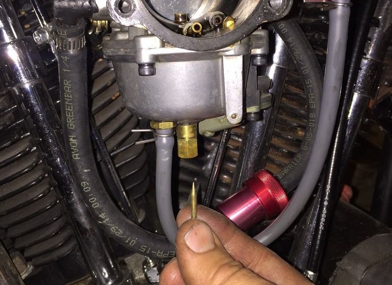
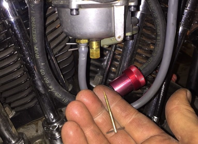
This replacement needle makes it so much easier to adjust the idle mixture. 19)
However, it is easier to count the turns by hand with this mod.
A spigot was added to the face of the knob.
The needle was screwed in all the way to gentle seat.
Then the side nearest the air cleaner (right of bike) was marked to index when to stop turning to the right.
The needle was then removed, drilled and tapped (10 BA) for the spigot.
You can also drill hole through the knob from side to side and Superglue a screw in it. 20)
The EZ-Just makes it easy to adjust the idle mixture by hand without a screwdriver.
But, if you've gone 3 to 3-1/2 turns out, then change to the next biggest slow jet. 21)
| Spigot installed to count the turns. 22) |
 |
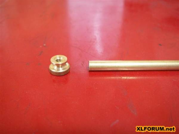
Modding a Factory Mixture Screw
This was done to extend the factory idle mixture screw.
A piece of 3/16“ brass tubing and a knurled nut from the hardware store.
| Factory idle mixture screw extended. 23) | |
 |  |
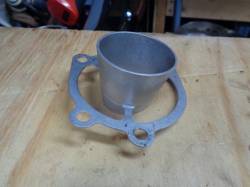
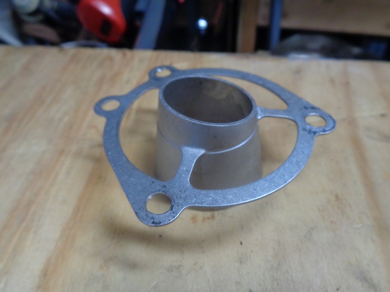
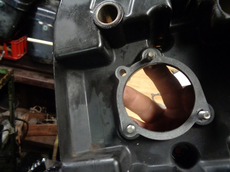
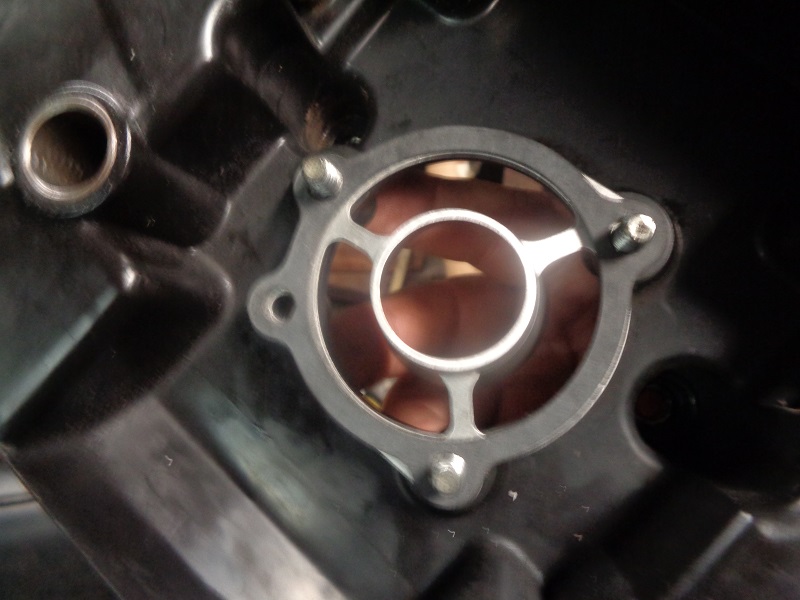
Velocity Stack
A velocity stack has been used (between the air cleaner and carb) to reduce turbulence while increasing velocity for optimal fuel mixture. 24)
It's doesn't block or reduce air flow and is suppose to greatly improve mileage by encouraging a more complete burn of the air/fuel mixture.
“Bolt-on performance that installs in minutes” although no performance enhancements have been found while using them.
Aluminum type velocity stacks like the “V-Ductor” from CV Performance have been used and tested to find no HP gains from them.
Some may still cite 'peace of mind' and there is no downside to using it other than the price.
It requires a total of 2 gaskets (included) to install. 25)
 |  |
 |  |  |
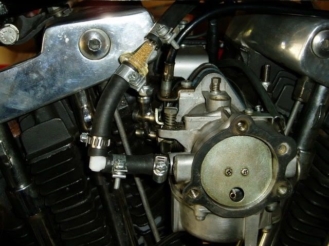
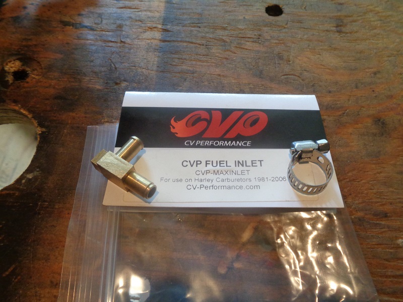
Replacing the Plastic Fuel Inlet Fitting with a Brass 90 Degree Fitting
The factory fuel elbow found on Keihin carburetors has been prone to cracking and leaking.
Also the manner in which the plastic elbow is formed onto a brass insert restricts flow.
It's made of a combination of molded plastic on the outside with a brass nipple installed on the inside of the carb.
The plastic attached to the brass nipple can crack or break off when removing the original crimp clamp or if over tightened.
Stress can also break it while removing / installing the carb if the attached hose gets caught on something and pulled.
Replacing the factory elbow with a brass one can increase gas flow (especially with a vacuum-less petcock).
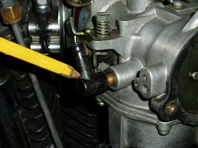
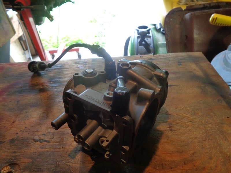
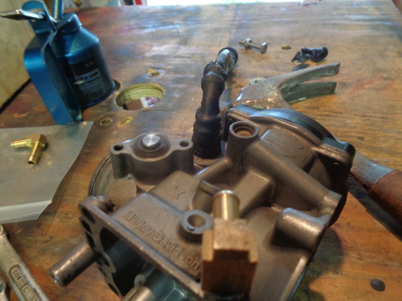
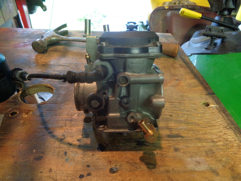
| Factory plastic fuel inlet elbow on Keihin CV. 26) |
 |
| Keihin butterfly (non CV). Here is on way to do it. Break the plastic off and run a hose on the factory brass nipple. 27) | ||
 |  |  |
Replacing the the hipple with a brass elbow is detailed below.
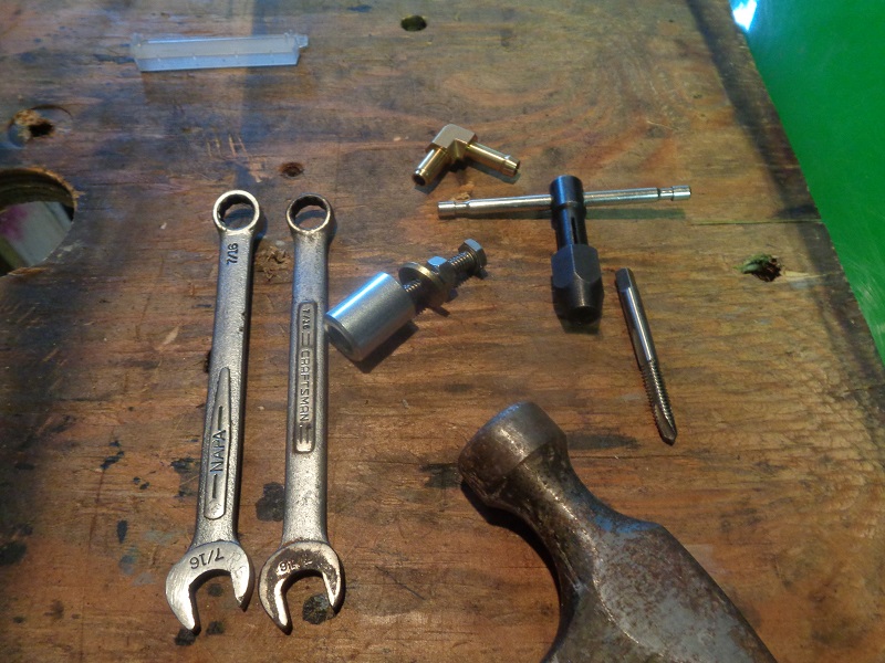
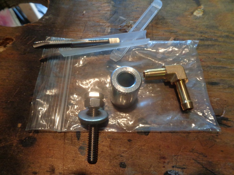
Tools
- 1/4”x20 tap
- Tap handle
- (2)-7/16“ wrenches
- 1/4”x20 bolt w nut and washer
- Spacer (or a socket can be used instead)
- Hammer
- Bench vise with soft jaws (can be optional but handy)
Part Considerations
- Brass 90° elbow
You need an elbow designed for this application for best results.
The MoCo may still sell both an OEM and brass inlet (27371-76a) that can be pressed in (arbor press or large vise).
You can search the brass elbow part number online. Some catalogs carry an OEM replacement inlet but it has the same plastic elbow (not recommended).
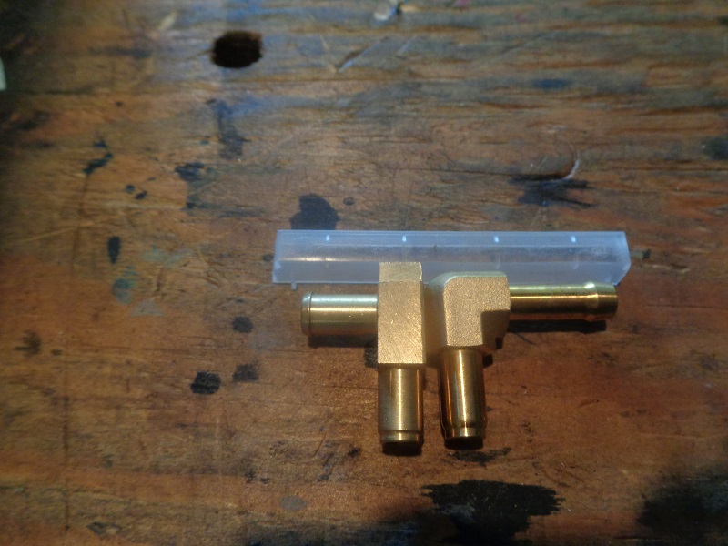
While others sell a brass inlet made from a 2-piece design (also not recommended).
CV Performance sells a solid elbow and a hose clamp as a kit.
You can also buy a kit on the internet / Ebay that includes the tap, bolt and spacer setup along with a solid elbow.
Or check your local Harley Dealership for a replacement elbow.
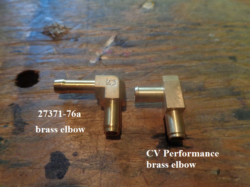
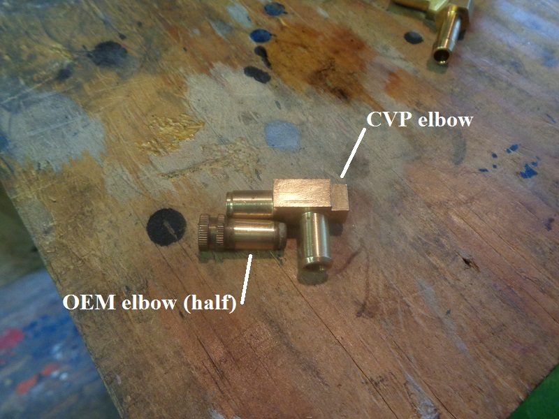
There are differences in these two elbows and those differences can be a factor in how it is installed.
However, either will work fine. Below are some considerations when installing.
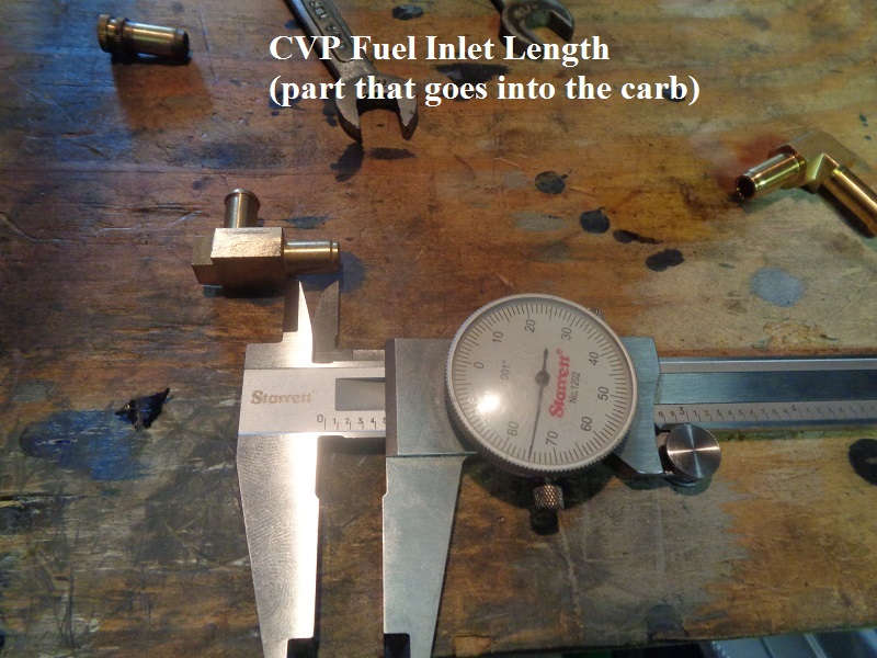
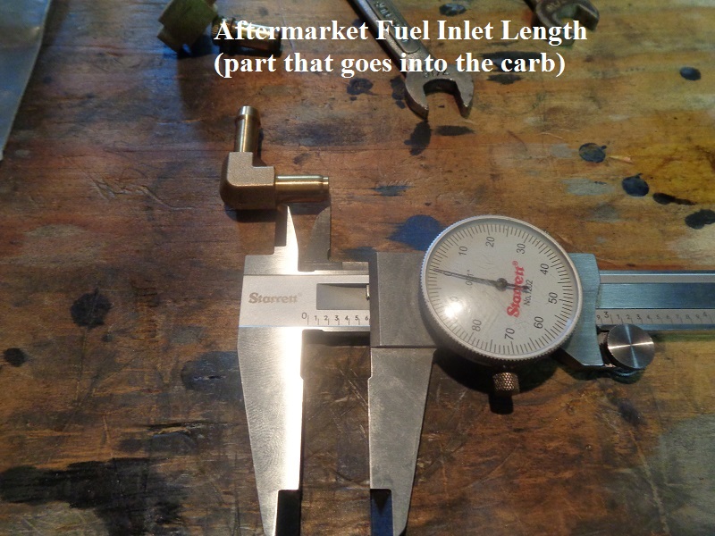
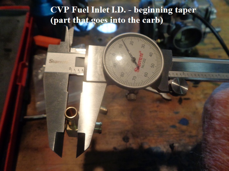
The CV Performance elbow has a shorter end going into the carb than the other one. It's also tapered.
This allows you to set the elbow horizontally into the carb without a tilt and get a loose fit to adjust the direction before pressing it in.
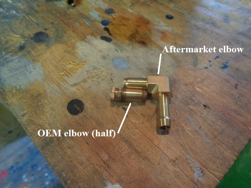
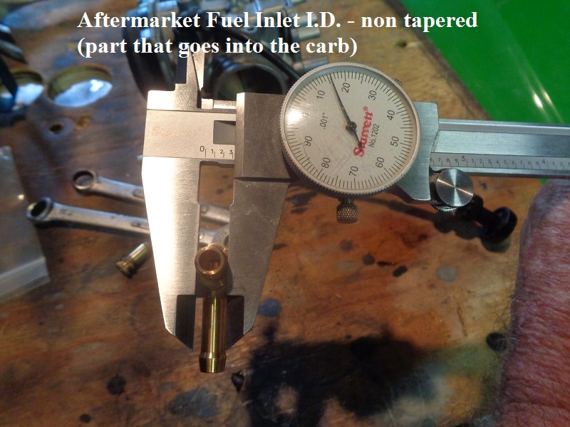
The other elbow is more consistent with the original length, not tapered and will provide more holding area through the entire shaft.
But it will sit in the hole at a tilt until it is pressed in somewhat so the angle needs to set before you install it too far in the hole.
The CVP elbow has a flat at the bend for ease installing it in a bench vise although with the taper, it is relatively easy to tap in place with a wrench or hammer.
 |  |
 |  |
 |  |  |
 |  |  |
 |  |  |
The Process
The carb below is a Keihin CV from a 98 S model but the process for replacing the elbow is the same for all Keihin carbs.
It's a fairly simple job to replace the fuel inlet.
Instructions are also here at the CVP website: https://cv-performance.com/harley-fuel-elbow-replacement
Notes:
While working on the carburetor or any fuel system, care should be taken to keep away from any open flame or heat source.
Never try to loosen carburetor parts using heat.
Do not use brute force or methods other than a puller.
D0 not remove the inlet from the carb using a drill or vise grips.
This could damage the body or distort, crack or broaden the hole where the new inlet presses into.
Follow all safety precautions.
The following instructions are provided as a basic guide and assumes no liability for any damages or injury.
Never work on a carburetor or related fuel system in the presence of an open flame or heat source.
Prep:
The cover doesn't necessarily have to be removed, but it's best to be able to blow out the passage with it off.
Be sure to first mark or note the position/angle of the factory elbow before removing it.
The replacement elbow should installed in the same direction to keep your original fuel hose routing.
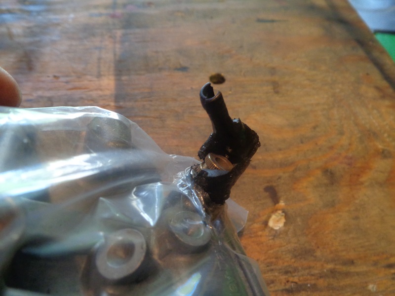
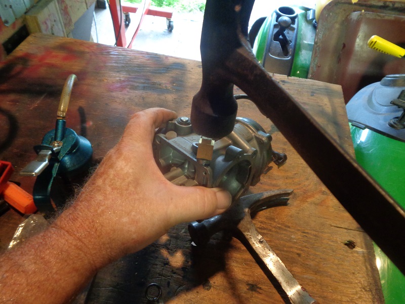
In order to remove the original fuel inlet you must first break off the plastic molded elbow.
Don't be shy, get out your favorite hammer or pliers and simply snap the plastic portion off of the carb.
It is important to first note the angle/position of the original elbow so the fuel line is routed correctly when reinstalling a new elbow.
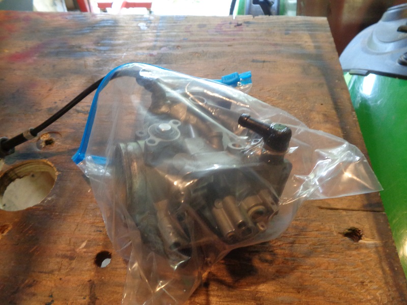
You'll be using a hammer to break off the plastic elbow so make sure to cover the carb to keep out any debris generated.
CAUTION:
Never heat a carburetor to remove or loosen parts.
Holding the carb in your hand with the plastic fitting on a bench / table won't jolt the body / insides as much.
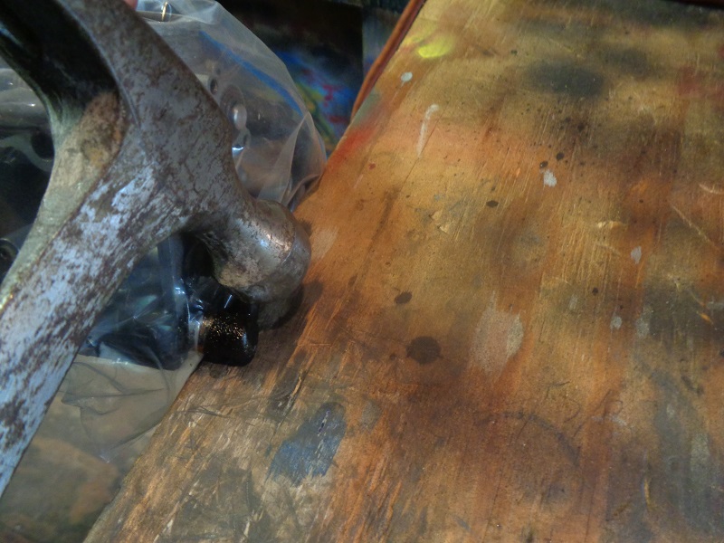
Using a hammer, strike the upper part of the 90° elbow past the 90° joint (nothing but plastic here).
The plastic may break off in various ways, thus the plastic bag over the carb was used here. 33)
 | 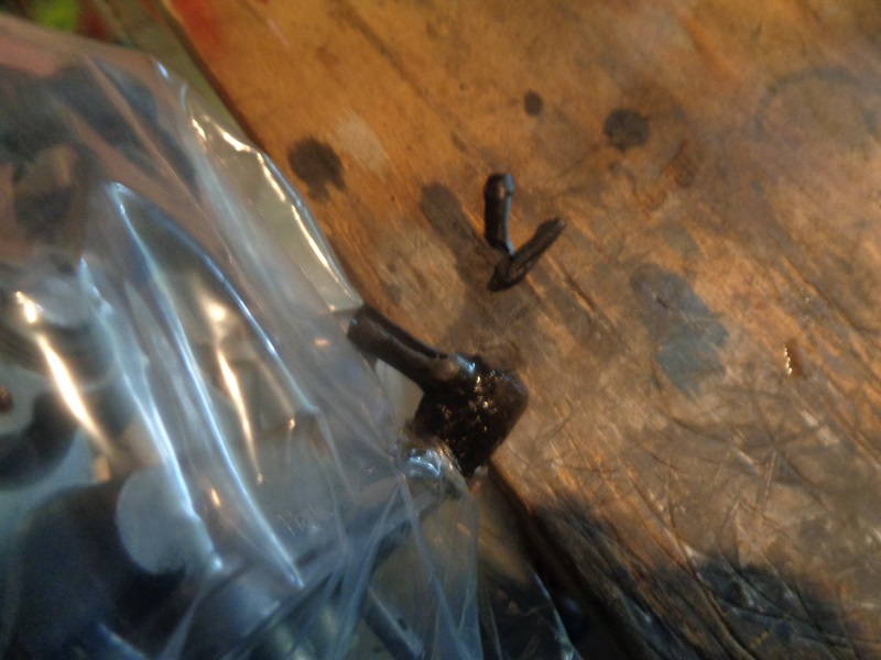 |
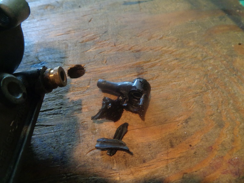
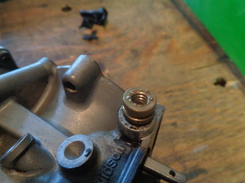
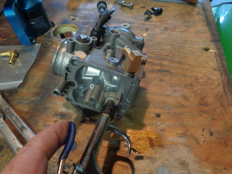
Once the end is broken, you can try peeling the plastic off the brass nipple to expose the end. 34)
 |  |  |
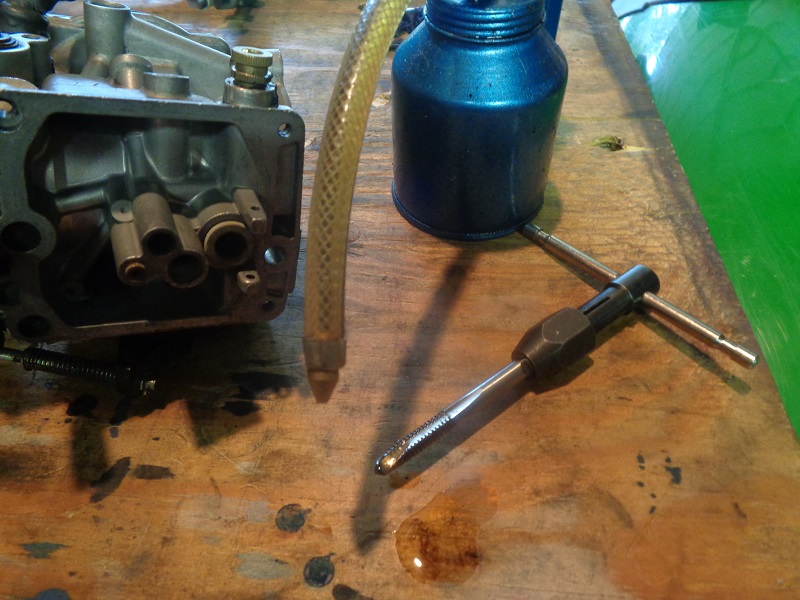
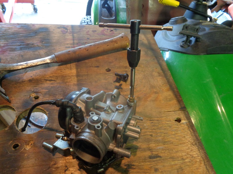
Assemble the 1/4“-20 tap, tap handle and lube the tap. The I.D. of the nipple is already sufficient to accept the tap.
(no drilling required)
Insert the tap into the nipple and begin threading it clockwise turning in approximately 1/4”.
Tapping threads all the way through is not necessary as you only need enough for the bolt to grab while pulling the nipple out.
To prevent excess brass particles from falling back into the carburetor with the bowl on;
It is advisable to hold the carb with the inlet piece facing down so that particles fall away rather than being pushed into the bowl.
This is not necessary with the bowl off as you can blow the passage out from the inside.
 |  |  |
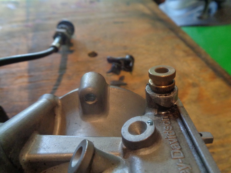
Remove all brass cuttings / particles after tapping and before continuing.
 35)
35)
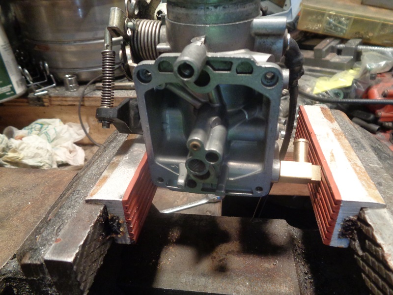
Assemble the puller:
I pre-made puller was bought for the pics below.
But you can also use a 1/4'x20 threaded rod about a foot long screwed into the fitting.
Then slip a thin piece of pipe nipple over the rod with a washer and nut onto the end of the rod. 36)
Place the spacer (or deep socket) over the brass nipple.
Thread the nut onto the bolt up to the screw head then add the washer.
Insert this assembly through the spacer and thread the bolt a few turns into the tapped brass piece.
You only need a few threads in to grab.
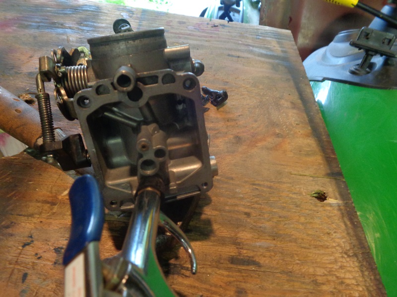
With a wrench begin to turn the nut down (clockwise) forcing the screw to lift the brass piece out.
It may be easier to hold the bolt with one wrench and turn the nut with another.
Once the piece begins to move it will pull out like butter. 37)
Once the nipple is out, you may have to 'pop' the spacer of as it may wedge against the carb.
A socket may be used as a spacer with the appropriate length bolt.
![]() 38)
38)
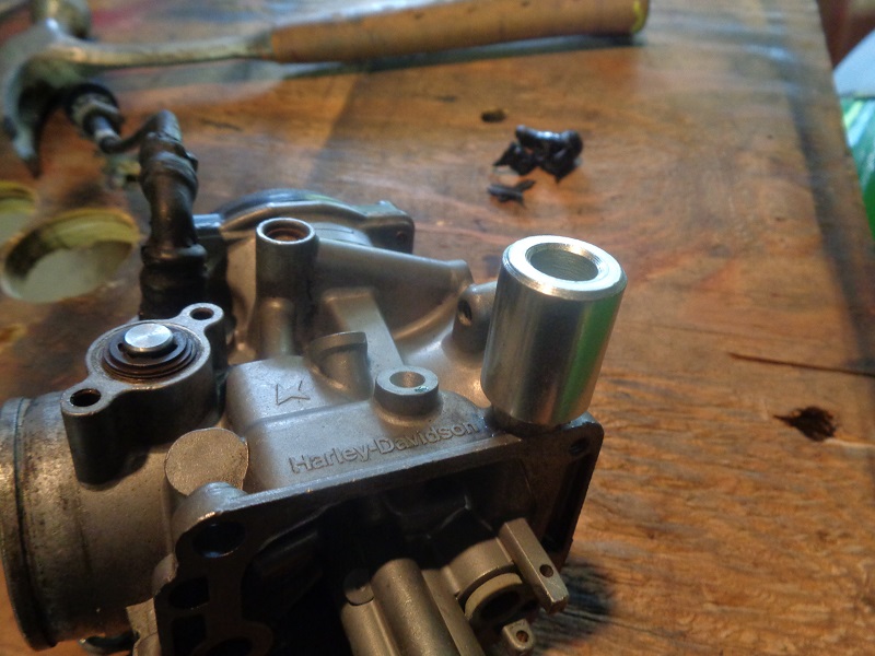


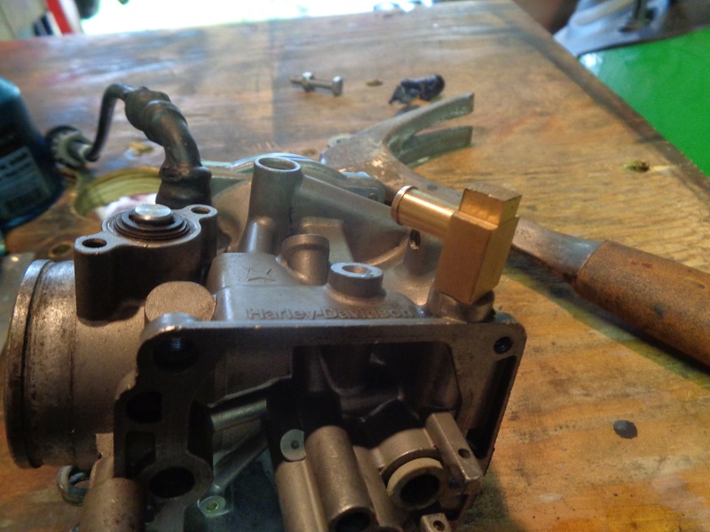
Thoroughly clean the fuel insert passage to make sure it is free of any brass filings.
Soapy water will wash away any fine particles and not harm the internal parts.
Compressed air will also blow out the passage.
Be sure the carburetor is clean and dry.
39)
Installing the new fuel elbow will vary depending upon brand or type of elbow used.
Position the inlet elbow in the same direction as the original so that the hose can be routed correctly.
If installing a solid brass or CVP inlet and a press is not available, simply tap the inlet into the carburetor with a small mallet.
You may also place a piece of wood over the elbow and tap in with a regular hammer.
The smooth end presses into the carb and the barbed end is meant to grip the fuel hose.
If you're to tap the elbow in, hold the carb in one hand and tap with the other.
This will take the blow off the carb body and internals.
| Double check alignment before installing. 40) | Tap the elbow in with a hammer. 41) | Or pull it in with a vise with soft jaws. 42) |
 |  |  |
The brass inlet will self-seal when pressed in as long as the carb inlet passage hole is free of debris and not damaged, stretched, or cracked.
A thin layer of blue locktite may be applied around the fitting to help seal.
But care should be taken not to allow any to drip back into the fuel passage as it will damage the rubber tip on the float needle (plunger). 43)
Blow the passage out again to ensure of no debris before installing the bowl. 44)

Adjustable Main Jet (L76-87)
There is an adjustable main jet available from J&P Cycles or others.
These work great and you don't have to fool around jet guessing whether you have the right size main jet or not.
They are simple to adjust. Just wind it up to about 65 MPH and run it in until it misses and back it out about a full turn. 45)
This kit can be purchased online. It comes with an installation guide and index pointer.
The tool marks inside of the float bowl (as installed) for drilling the proper sized hole to thread in the adjustable main jet.
The kit can be purchased online.
PDF instructions - http://www.vtwinmfg.com/instructions/35/35-0369.pdf

This replaces the main jet (has to be removed).
The float bowl has to be removed to install the adjustable main jet.
A guide tool is included with the kit to install the new jet to properly index the carburetor float bowl.
A index pointer is installed in the guide, bowl reinstalled and the pointer is pushed down from inside the venture to dimple the bowl.
The bowl is once again removed and a 1/16“-1/8” pilot hole is drilled followed by a 15/64“ bit.
After checking for burrs, removing the index tool and guide and cleaning up, the adjustable jet is installed in the float bowl.
(partially unscrew the small 'T' handle so that the needle in the adjustable jet is not exposed to accidental damage)
Remove the nut from the adjustable jet, insert the jet through the 15/64” hole drilled earlier.
Then re-tighten the bowl and gently screw in the 'T' handle to the needle seat and then back it out 4 turns.
Finer tuning can be achieved by reading the spark plugs and small adjustments to the “T” handle.
This adjustable jet eliminates the chore of carrying and continually changing different main jets with every change in exhaust system or air cleaner.
The hole in the bowl for the 'T' handle jet has to be indexed correctly in order for this to work.
The adjustable main jet is designed to operate in conjunction with a 1.80 main jet included with the kit.
Make sure you record or remember the number of turns off the seat and back off the 'T' handle before removing the float bowl later.
This will help prevent needle / jet interference when the float bowl is reinstalled.
For initial adjustment (standard pipes and A/C) it's recommended that the adjustment needle be backed out four (4) turns from the seat.
The adjustable jet set screw is turned in, towards the float bowl to lean the fuel/air mixture and out from the float bowl to richen the mixture.
Check plugs frequently after jet adjustment, exhaust or A/C to avoid too lean or too rich conditions.
 |  |
Andrews High Flow Accelerator Pump (Keihin butterfly)
Installation instructions from Andrews is here.
Features: 46)
- Improves throttle response
- Larger fuel volume/discharge
- Fits 79-89 H-D using Keihin carburetor (except Flowmaster and CV)
- Easy to install
- Fits 79-89 H-D with Keihin carb
- Dimensions: 5“x3”x1“; 0.3 pounds
A high flow accelerator pump is also a great all around upgrade for these carbs. 47)
 48)
48)  49)
49)
How the High Flow Accelerator Pump should be installed: 50)
- Remove float bowl from carburetor. There are four screws holding it in place.
It is not necessary to remove the entire carburetor from the engine to install your new high flow accelerator pump. - Clean any fuel residue from the bowl assembly and remove the stock accelerator pump housing.
It is held in place with three screws but one of them already has been removed with the bowl. - Position the bowl upside down for drilling a single hole through the bottom.
- Any drill of approximately 1/16 diameter will be quite satisfactory.
The exact location for this hole is already marked with a dimple on the bottom of the float bowl casting as shown in photo below.

- Feed the drill through until it breaks out into the float chamber.
Don’t worry if the hole breaks into either a cross drilled passage or through the actual bottom of the bowl.
The location is not critical as long as fuel can feed through into the accelerator pump. - Thoroughly clean any drill chips from the bowl. There is a small bypass hole in the bottom of the bowl which does not have to be plugged.
Several earlier magazine articles have recommended plugging this hole but there will be no measurable benefit from doing so. - Install the new accelerator pump housing onto the bowl with the two shortest screws of the original three.
Make sure that the two small O-ring seals are installed;
One into a recess in the pump housing.
The second into a recess into the bottom of the bowl casting. - If the accelerator pump jet needs to aimed differently, now is the time to do this.
With a small adjustable wrench, carefully reposition the pump jet by gently turning it in the bowl casting (it’s a press fit). - Reinstall the bowl and pump assembly back onto the carburetor body to complete the job.
The extra fuel from the larger capacity pump should result in smoother, quicker throttle response especially off idle or at low RPM.

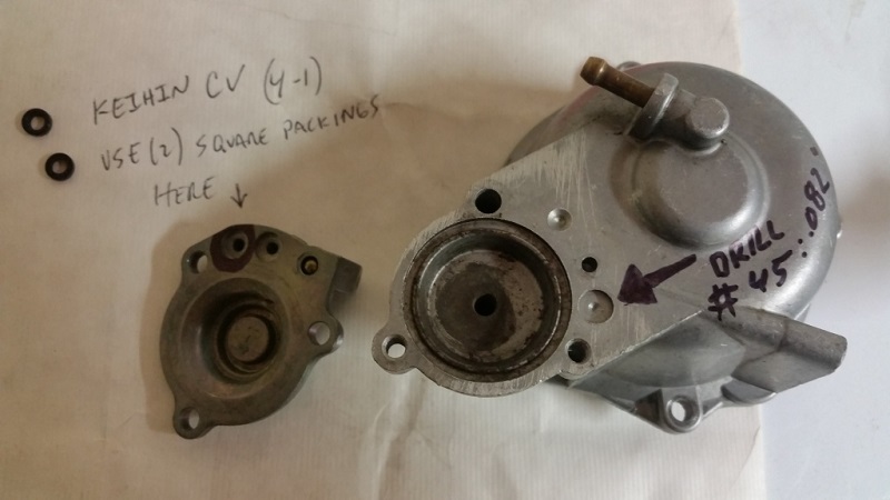
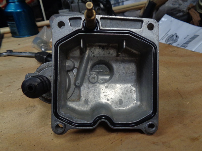
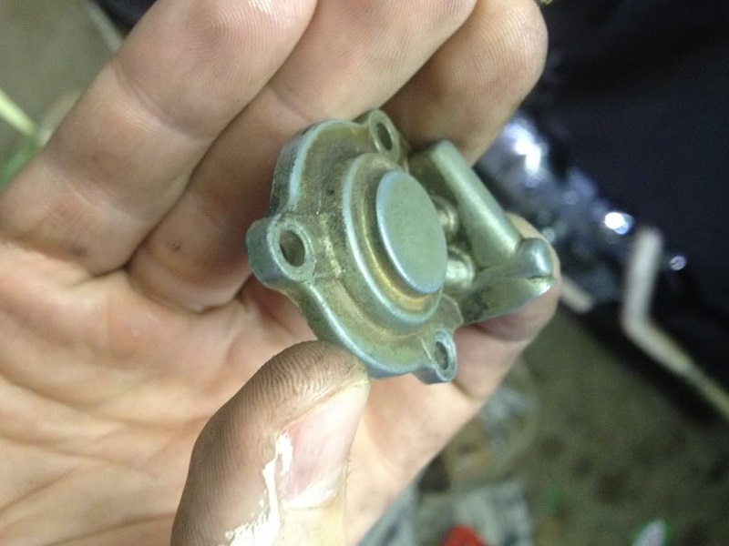
Alternative using CV accelerator pump:
It looks like Keihin made all these covers so any of the basic raw castings can have additional operations incorporated to be used in any of their many configurations. 51)
The stock pump cover for non CV Harley carbs (2-2) uses the same passage for supply and pump shot.
The high flow cover uses separate passages for supply and pump shot (4-2).
It also contains a loose check ball in the passage.
The stock cover is not easily owner modified to incorporate separate passages and check ball (2-2).
The Keihin CV pump cover (4-1) (left in center photo) is a high flow cover just as the Andrews.
The only difference is the (4-1) cover has an extra counter-bore compared with stock non CV.
The CV cover is made with packing bore in cover.
The non CV is made with packing bore in bowl body.
It seems the CV (4-1) cover can be made to work in a non CV if (2) square packing are used, one in cover and one in carb body.
Note: All orifices in covers are the same.