
REF: Engine Mechanicals - Sub-01R
Disassembling the Crankshaft / Flywheel Assembly
See more crankshaft / flywheel tools in the tools section of the Sportsterpedia.
Article by Hippysmack
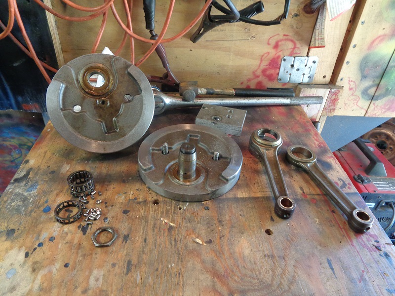
This is a 91-99 flywheel assembly but the process is basically comparable for 03 and prior flywheel assemblies.
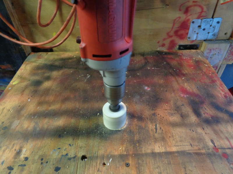
The table is a 3/4“ piece of plywood hinged to the wall with a 2×4 stood up under it.
To make it easier, no measuring of the holes was done.
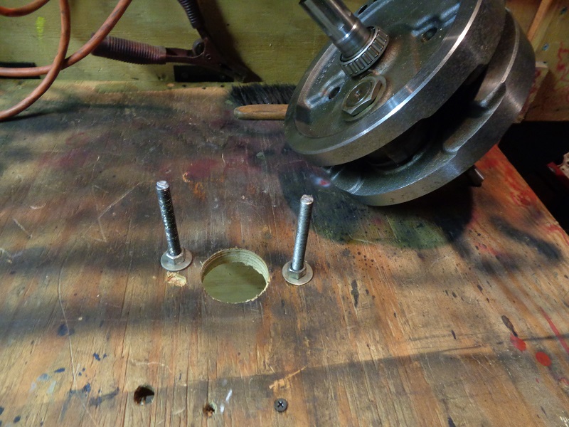
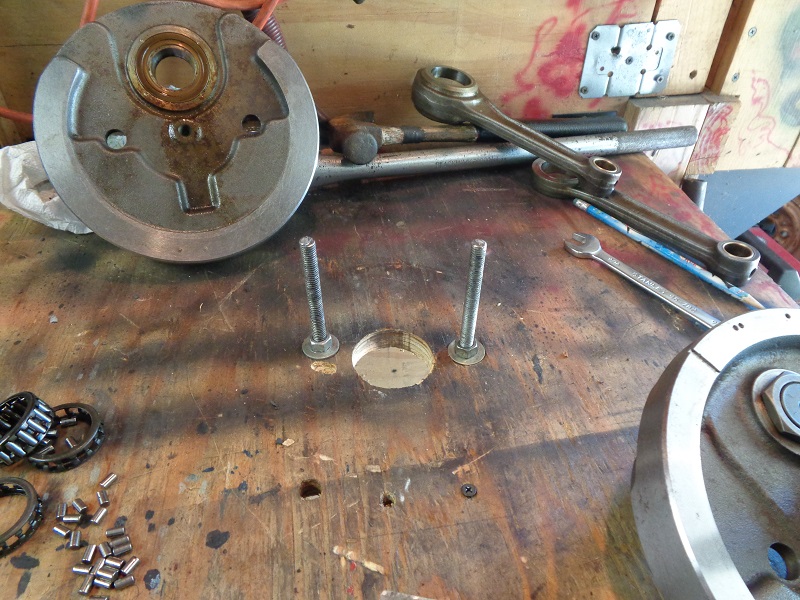
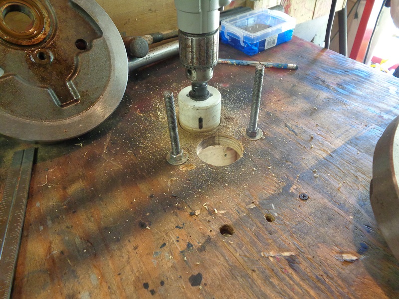
A 2” hole saw was used to bore a hole for the pinion shaft to sit down in.
The size of the hole isn't really critical as long as it's bigger than the shaft.
The 2“ hole just gives some leeway to position the wheels to drill for the holding pins.
Then a 3/8” drill bit was run into the holes to the board to mark the hole locations.
 | 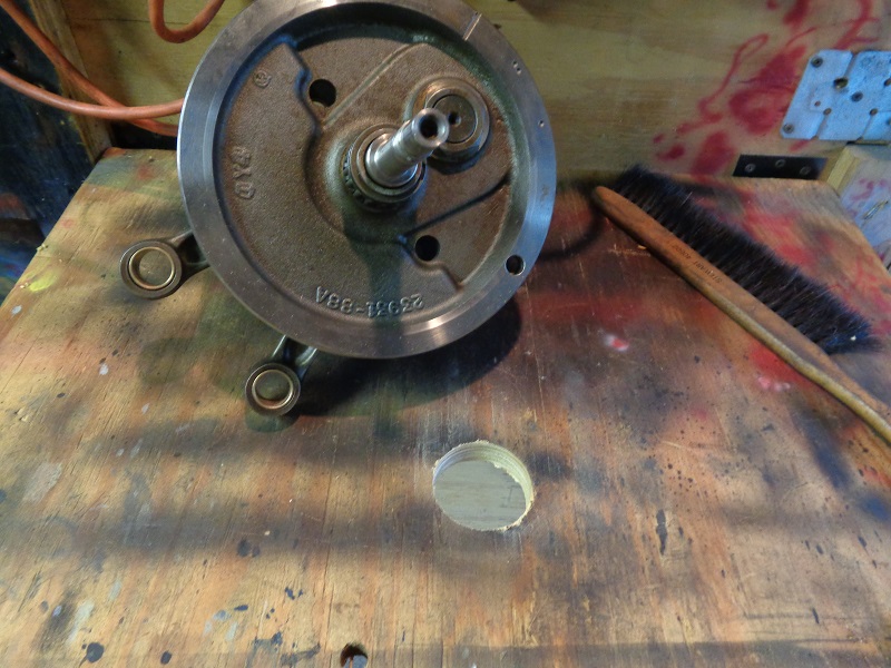 |  |
The location can be adjusted if needed before drilling the holes.
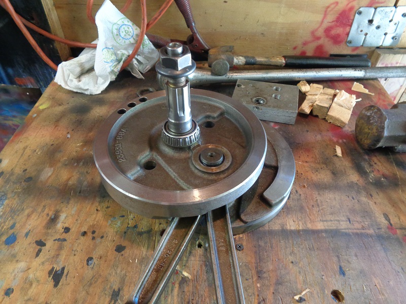
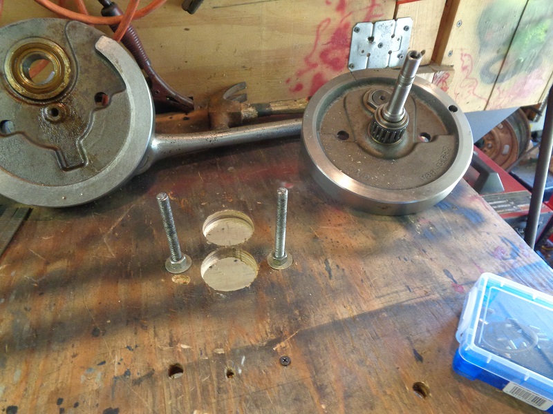
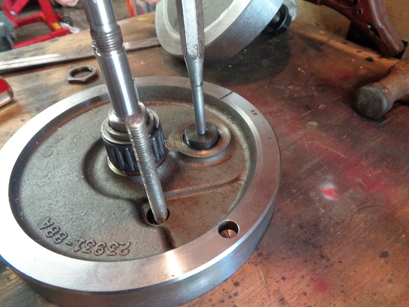
Once the holes are drilled, run 2 pieces of 3/8“ x 12” threaded rod into the holes with nuts and washers on top and bottom.
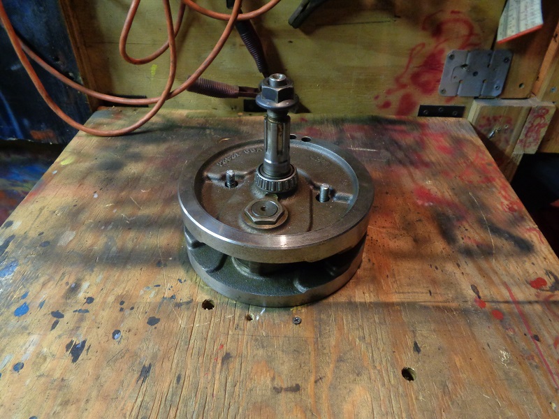
Make sure they're tall enough to go through the holes in the top wheel.
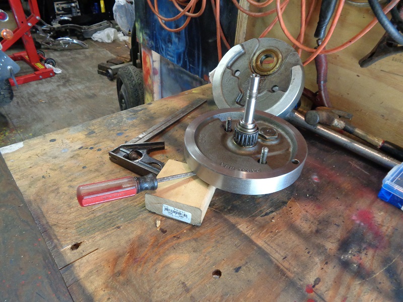
Then set the wheel over the all-thread (or holding pins).
 |  |  |
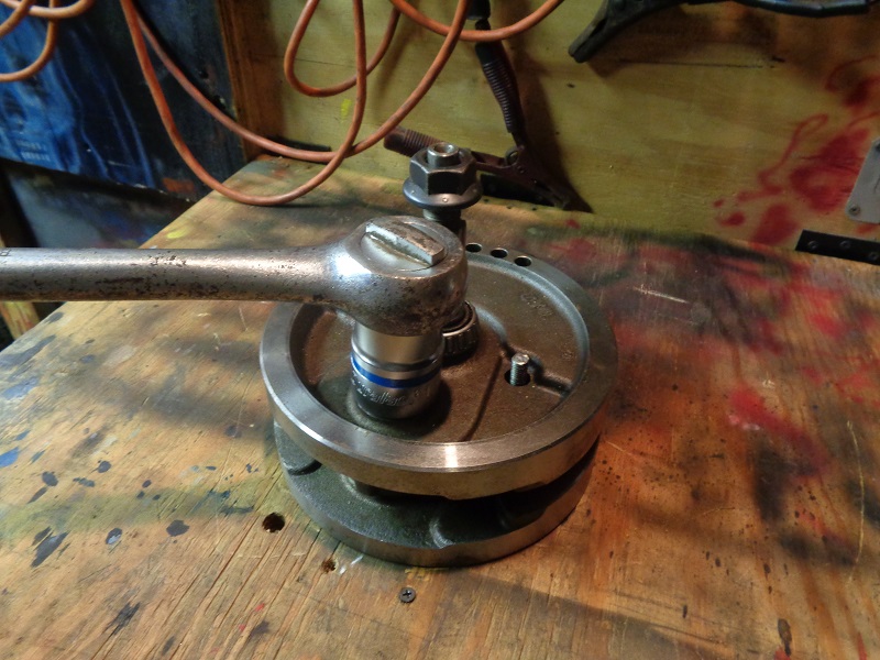
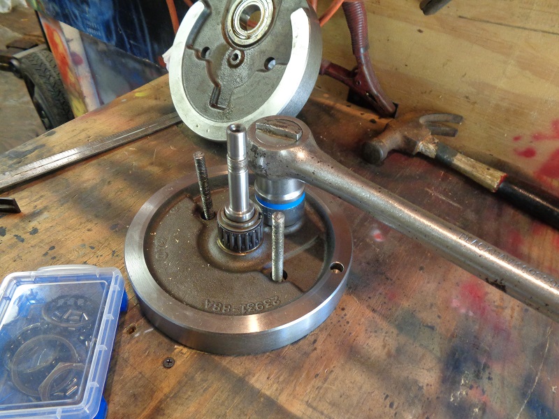
Use a 1-5/16“ socket wrench to remove the crank pin nut on the sprocket side.
With the crank nut off, lower the all-thread below the top wheel and retighten the nuts.
You'll be knocking the top wheel sideways next to loosen it from the crank pin.
 |  |  |
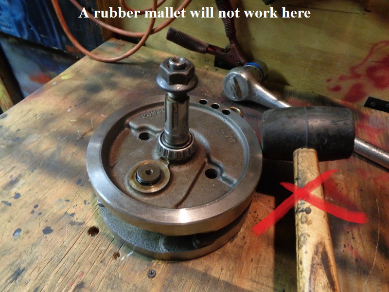
Double check that the holding pins are below the top wheel.
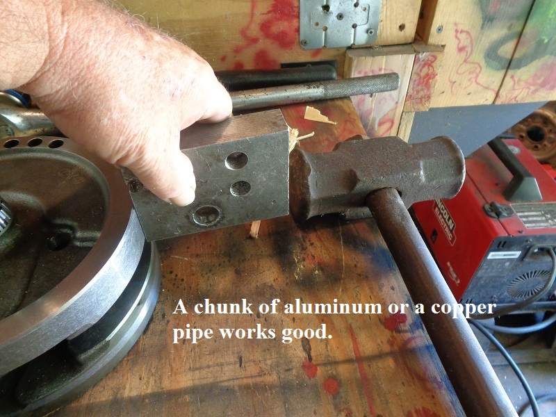
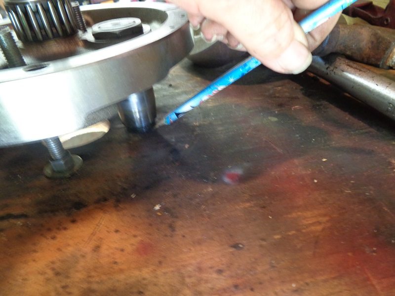
Do not attempt to hit the hardened flywheel with a steel hammer alone.
You need to use a soft metal hammer (brass, lead etc.) to keep from exploding the flywheel into your body parts.
A sledge hammer hitting a block of aluminum against the wheel was used below (a rubber mallet will do you no good in this instance).
Hit the top wheel 90º to the crank pin hole on the outside edge to knock it sideways and loosen itself from the crank pin taper.
Basically hit the outside edge in the vicinity of the holding pin hole. The soft metal will not hurt the flywheel.
 |  |  |
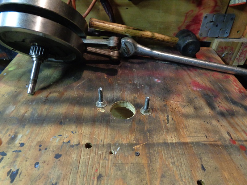
It takes a pretty good whack to move it and swing it off to one side.
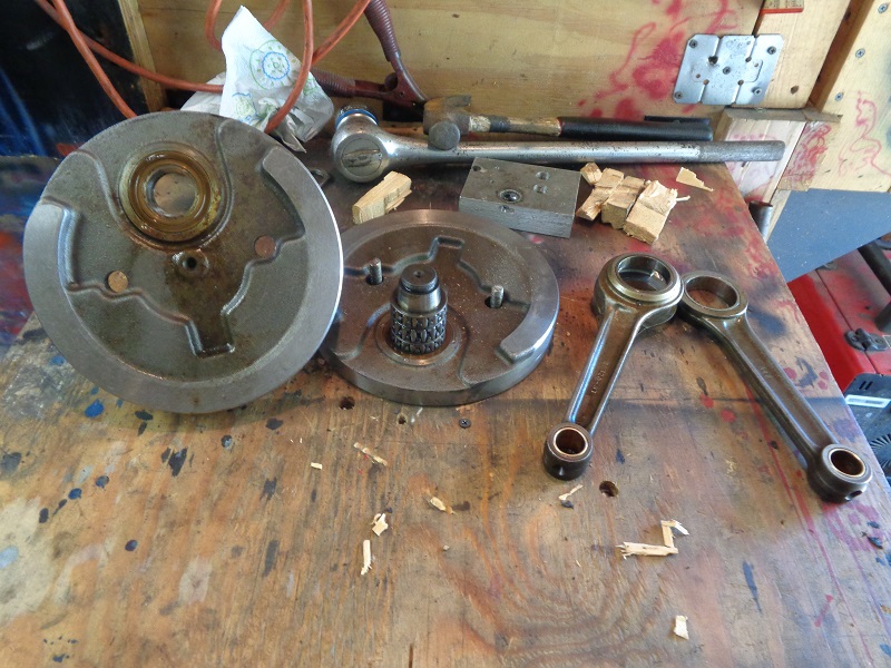
At this point, you can lift the top wheel off the assembly.
Note: Use a short piece of pipe (O.D. no bigger than the bearing cage) over the crank pin and against the top bearing cage.
(else the small bearings will fall out and scatter when you pull the rods up)
That was not done here and bearings did scatter.
Then remove the connecting rods.
 |  |
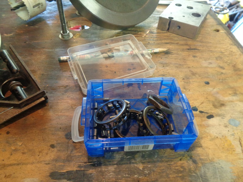
The bearings and parts will go everywhere so it's best to have a storage container of sorts to keep them in until you're ready for reassembly.
 |  |
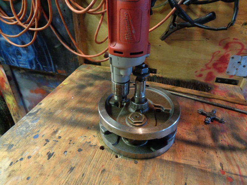
Next, the jig has to be drilled to accept the crank pin and allow the bottom flywheel to sit over the holding pins.
The wheel was placed over the pins, leveled and the crank pin location outlined.
 |  |  |
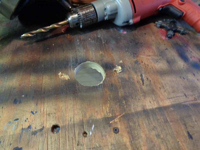
Then another 2” hole was made into the outline for the crank pin.
Lower the wheel into position and the nut can now be removed with the 1-5/16“ socket.
 |  |  |
Then, knock the pin out with punch and hammer (make sure there is something soft under the crank pin for it to land on).
Again, it'll take a good whack to dislodge the crank pin.
 | 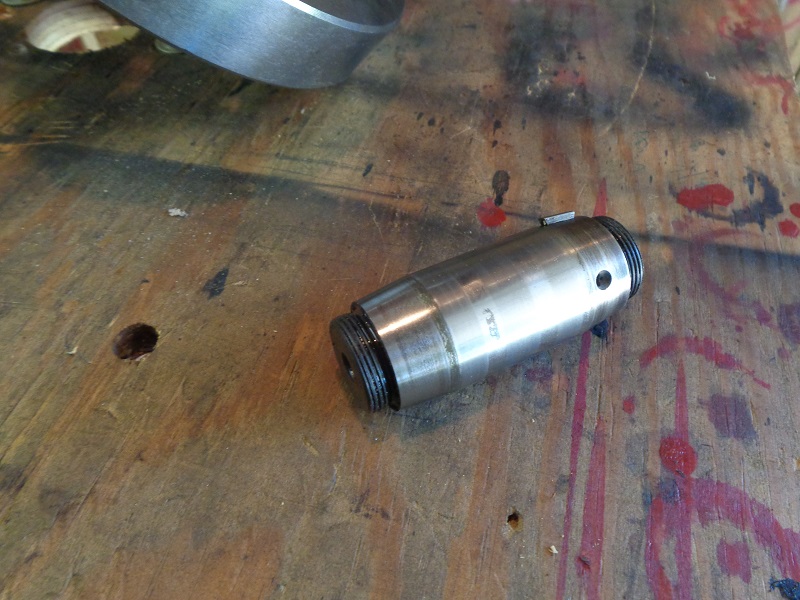 |