This is an old revision of the document!

REF: Engine Mechanicals - Sub-04K
Breather Valves (1957-Up)
See the respective sections in the Sportsterpedia for the different breather valves used on Sportsters.
List of breather valve changes per year model:
1957-E1984 engines incorporated an oil slinger (spinning gear or washer on the generator drive gear) to separate oil from air before running to the vent tube.
1957-1976 models: 1)
There is a timed breather valve built into the oil pump drive, which vents both oil and crankcase pressure into the cam timing chest.
A six-inch metal tube hanging down from the timing cover near the generator drive, at the 6 o’clock position vents that controlled pressure to atmosphere.
A metal gear or washer on the end of the generator drive gear centrifugally separates oil from the air as it is discharged overboard.
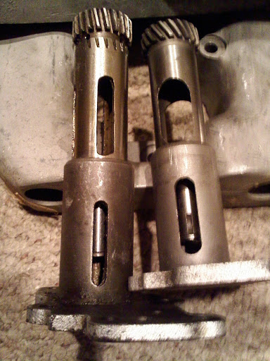
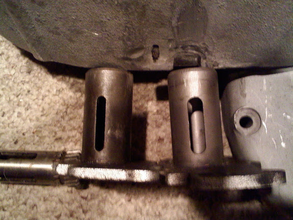
The rotary breather valve on the oil pump that is timed to open on the downstroke of the pistons. 2)
This allows crankcase exhaust air pressure and scavenge oil in the crankcase to be expelled from the crankcase to the breather oil trap and into the gearcase.
The breather valve closes during piston upstroke, creating a controlled amount of vacuum in the crankcase.
The 1952-1971 breather valve opens at 77° (ATDC) and closes 67° (ABDC).
The 1972-1976 breather valve opens 20°-25° (ATDC) and closes 85°-90° (ABDC), less duration than the 57-71 breather.
| Left is the unmodified 1/4 speed R valve. Right is the 1000 stock. | R model is the left one. |
 |  |
1977-78 models only: 3)
The timed breather on the oil pump drive was dropped.
Without the breather gear that means you have less control of the oil / air density in the crankcase.
An external non-return valve was plumbed into the breather vent tube sticking down from the timing cover at the generator drive.
This allows air out, but not in. It is sometimes referred to as the foo-foo valve.
The valve is installed on the outboard side of the gearcase and inside a threaded fitting with no oil separation drain back hole.
1979-Early 1982 models: 4)
The external foo-foo valve and the six-inch metal vent tube at the front of the timing cover were done away with.
Instead, a one-way reed valve (assembly, 26909-79A) was built inside the timing cover.
A rubber breather hose then ran from the generator drive area of the timing cover, at the 10 o’clock position.
It connected to the stock air filter so that any oil mist was fed back through the engine.
This made the EPA more happier than they were with the idea of engine oil spraying out into the atmosphere.
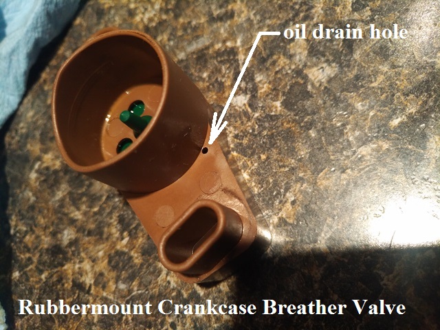
The cam cover has an oil drain back valve built into the breather valve compartment.
This allows accumulated oil that gets past the valve to drain back into the gearcase.
Late 1982-Early 1984 models:
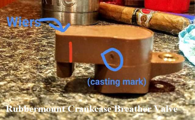
The internal crankcase breather valve was redesigned to incorporate a rubber umbrella valve.
This is attached to the base plate along with a larger diameter (1-3/4” O.D.) oil separator washer on the generator armature. 5)
The cam cover has an oil drain back valve built into the breather valve compartment.
This allows accumulated oil that gets past the valve to drain back into the gearcase.
There is a plug in the 6 o-clock position and a tube in the 10 o-clock position going to the air cleaner.
Late 1984-1990 models:
A breather baffle tube system was incorporated into the cam cover in the area behind the oil filter and the slinger washer is no longer used.
The baffle tube has a one way umbrella valve mounted into it. Crankcase exhaust (air and oil mist) is routed to the breather baffle at the front of the gearcase.
Oil is separated from the air pressure by the one-way umbrella valve. The cam cover has an oil drain back valve built into the breather valve compartment.
This allows accumulated oil that gets past the valve to drain back into the gearcase through that drain hole.
The air is then routed into the rear of the air cleaner via an oil hose to the gearcase outlet.
There is a plug in the 6 o-clock position vent position and a rubber hose in the 10 o-clock position going to the air cleaner.
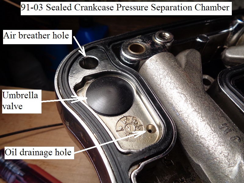
1991-2003 models:
In 1991, along with the 5-speed transmission, the MoCo moved the crankcase breathing from the cam box cover outlet to breather bolts in the heads.
Previously, these bolts were just used to mount the carb and air cleaner to the heads.
The new breather system uses one-way umbrella valves in the rocker boxes.
These exit crankcase vapors through vents in the top of the cylinder head into the carb mouth to be burnt. 6)
On each piston downstroke, crankcase pressure (air and oil mist) is routed up the pushrod tubes into the rocker box.
Collected air pressure and oil mist in each rocker box is routed up into a sealed cavity in the lower portion of the box.
This mixture passes up from underneath a rubber one-way valve (umbrella valve) sitting over the cavity inlet.
The oil is designed to separate from the air by hitting the underside of the umbrella valve.
Then dropping back down into a recessed area behind the umbrella valve in the cavity.
From there it should drain back into the main rocker box through a tiny hole behind the umbrella valve and then back to the lower end.
Air pressure is designed to continue up past the umbrella valve and exit a hole in each head on the intake valve side.
Air pressure escapes the head through the hollow bolts (one in each head) that hold the air cleaner mount.
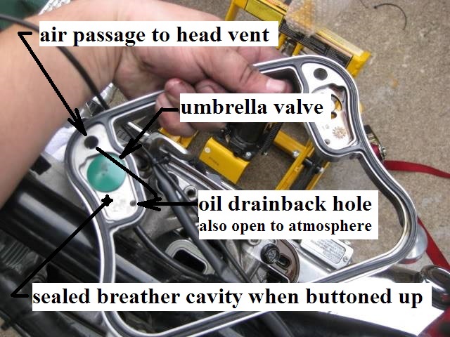
The 91-03 umbrella is sitting on the middle box spacer inside an enclosed cavity when it's buttoned up.
But this cavity has a tiny oil drainback hole on the left side of the umbrella.
So, if you blow into one head vent (carb bracket off and umbrella in good shape), the air comes out the other head vent.
There is the restriction of the tiny hole you're blowing air into.
So you will have to pucker up to blow hard through it.
That being said, that tiny hole will allow a small amount of outside air back into the crankcase on piston upstroke.
As soon as the sealed cavity is drained from separated oil, the only thing left is outside air to pull into it.
(for a small amount of time until the piston falls again)
This, in affect, will add a slight atmosheric aide to the 'then' negative crankcase pressure.
Just as you can't pump into a container with no vent, you can't suck from a container with no back vent.
Gravity drain oil (heads / pushrod tubes) also has the force of suction to help pull it down on piston upstroke.
Likewise, that suction also helps to drain the tiny hole in the sealed rocker box cavity.
So the head vent also doubles as a back vent to help CC vacuum drain the sealed cavity on piston upstroke.
2004-Present:
In 2004 the MoCo made some changes to the umbrella valve configuration.
The umbrella was retained but now inside a plastic housing with a pre-umbrella oil separating screen (fiber mesh).
On 03< models, the oil is actually separated by the umbrella. The umbrella doubles as a one way air valve.
On 04> models, the oil is separated first by the mesh below the umbrella which frees the umbrella to be more of a one way air valve.
There is an extra oil chamber between the in and out of the breather assembly.
So it could be said that the 04-up breather valve has 2 stage separation with a small hole in the middle chamber to drain what gets past the mesh.
Each 'breather valve' is assembled into a plastic fitting that is sealed over the outlet hole in the lower rocker box to the head breather bolt.
The new breather valves were also accompanied with new style hollow air cleaner mounting bolts for the pressure to escape.
The new bolts are the same thread size as previous.
But instead of a simple hex, it also has a shoulder past the hex for an O-ring to be fitted between the hex head and the air cleaner.
The breathing system is functionally the same as 91-03 with the one-way umbrella valves in the rocker boxes.
These exit crankcase vapors through vents in the top of the cylinder head and into the carb mouth to be burnt. 9)
On each piston downstroke, crankcase pressure (air and oil mist) is routed up the pushrod tubes into the rocker box.
Collected air pressure and oil mist in each rocker box is routed up into the breather valve unit in the lower portion of the box.
This mixture passes up from underneath the breather unit.
The oil is designed to separate from the air by hitting the underside of the screen / umbrella valve and dropping back down into the rocker box.
From there it is routed back to the lower end.
Air pressure is designed to continue up past the breather unit and exit a hole in each head on the intake valve side.
Air pressure escapes the head through the hollow bolts (one in each head) that hold the air cleaner mount.
To keep the engine from pulling in air from the outside, HD fits the breather vent(s) with a check valve.
This way, the motor can exhale, but not inhale.
The reason for the check valve is not to keep it from pulling in dirt.
Any inhaled air is going to get pushed out again and take oil with it.
- We have check valves in the rocker boxes (or cam chest respectively) that are *supposed* to eliminate this.
If they aren't functioning properly, you'll get lots of oil out the breathers. - The valves themselves rarely fail (unless they get hard), but the casting they sit in is, well, a casting…not very accurate.
- Buell had a service bulletin years ago that talked about chamfering the umbrella valve hole to make it seal better.
(as a fix for excess oil in the air cleaner)
The breather valve not only has to work but it has to operate in sync with the action of the pistons.
It has to open with downstrokes and close (completely) with upstrokes.