Table of Contents
This is an old revision of the document!

REF: Oiling & Lubrication
Installing an Oil Pressure Gauge
The presence of oil pressure is usually measured by whether the oil light is on or not.
The so called, idiot light, simply lets you know that the oil pressure is high enough to actuate the oil pressure switch and then the light.
It does not indicate any amount of oil pressure over the cracking pressure of the check.
The check valve (or check ball, respectively) opens between 4-6 psi.
So at all times, the pressure gauge should at least read that much as measured at the oil pressure switch.
If it is not showing any pressure you need to find out why.
Do not eliminate your oil light, this is your first and best indicator of proper oil flow. 1)
Sportsters are dependent on flow volume instead of static pressure.
The most important pressure reading is 4-6 psi.
That is what it takes to get the oil past the check valve / check ball and into the engine.
This allows the pump to deliver it's flow volume into the engine.
Gauge Selection
Using the correct gauge means considering the gauge accuracy required at the pressure point being tested.
Low range pressure gauges will be more accurate on a hot engine when the oil is viscous and the pressure is low.
During a cold startup, the pressure will be higher due to thicker oil when cold.
Likewise, a 0-30 psi or 0-60 psi gauge will peg out on a cold startup which could possibly ruin the gauge.
But it will show a more accurate reading when the engine oil is hot and at low pressure.
Whereas a 0-100 psi gauge will be more accurate during a cold startup but less accurate during normal operation with hot oil.
Glycerin filled gauges will withstand more vibration than non-liquid gauges.
Testing Locations and Matching PSI Specs in the FSM
The FSMs for all years include suggested oil pressure figures for each model when testing.
Most FSMs suggest taking the oil pressure reading by removing the oil pressure switch and placing a gauge (or gauge line) there.
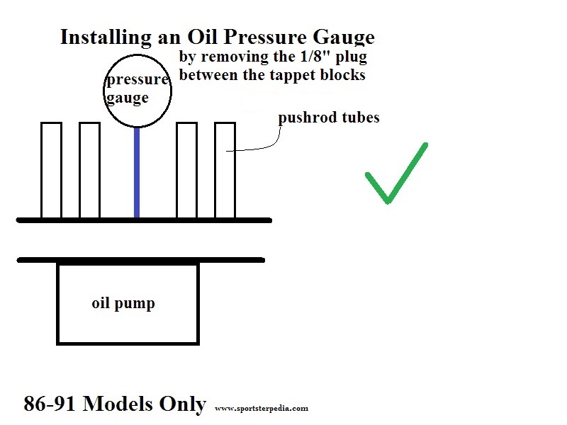
The exception would be 86-90 models with a reference also to 91 models testing between the tappets (see testing point illustrations below).
Due to the testing points that are suggested in the manuals, placing a gauge anywhere else won't provide any relevant information that you can compare to the manual
However, you can fit a gauge in other places to simply show some pressure for peace of mind prior to each ride.
The gauge should show some pressure even if it's not to par with the manual.
Some say an oil pressure gauge makes a nice back-up to the oil light though. 2)
86 and Up models
Testing per the FSMs
On 86-91 models, the 1/8“ plug between the tappet blocks on the right case is removed and the gauge hose is installed there.
These models have a pressure regulator built into the filter pad.
When the regulator activates, main oil pressure in the filter pad will be lower.
Testing from the tappet area will show actual working pressure to the engine without the high loss from the nearby regulator.
(main pressure will still be lower until the regulator closes)
However, the FSM also gives pressure readings for testing at the oil pressure switch.
On 92 and Up models, the oil pressure switch is removed and the gauge hose is installed there.
Oil is more restricted at the oil pressure switch location in the filter pad.
So oil pressure will be higher when tested at the switch location than when tested between the tappets or in the rocker box.
There also should no air in the feed line to compress and change the pressure readings.
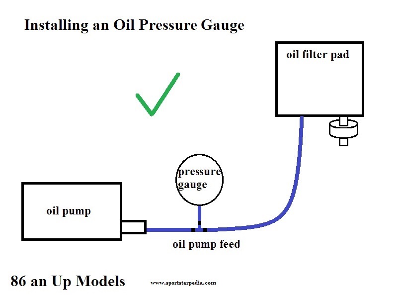
Below are some general drawings on hooking up the gauge. 3)
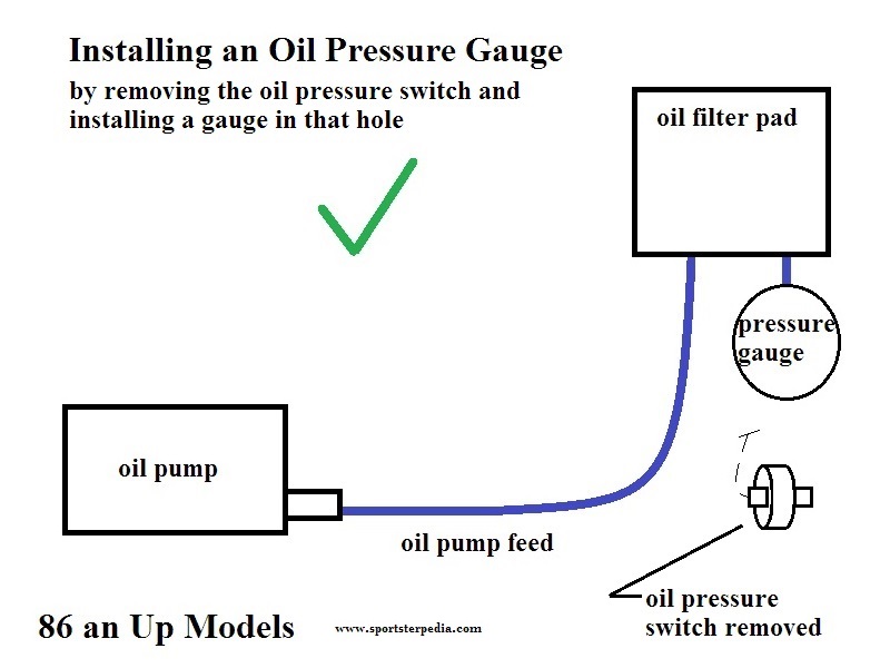

Between the oil pump and the filter
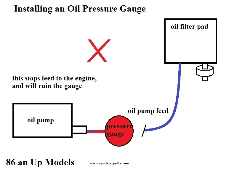
Do not test straight off the oil pump feed line.
Oil flow will stop to the engine and the pump will build enough pressure to destroy the gauge.

Rocker Box
A Sportster does produce oil pressure in the rocker box: reportedly 3-5 psi at hot idle and 15psi+ on cold startup on an ironhead. 4)
Depending on the gauge selected, there may be little to no oil pressure registered on a high range gauge testing form the rocker box.
(the gauge may show some pressure when the oil is cool and thick but may not show any after 5 minutes of running) 5)
Due to the low oil pressure at the rocker box,
Don't get scared when you look down after its hot and its on zero. 6)
- Residual crankcase pressure and working pressure from the lifters resides in the rocker boxes.
- On a cold startup, the pressure is higher due to the thicker oil present.
- As the engine warms up, the oil thins out and the pressure is reduced in the rocker boxes.
- Excess crankcase pressure (air and oil mist) is vented differently between pre and post 91 engines.
- On pre 91 engines, excess crankcase pressure is vented through the cam cover.
- On post 91 engines, excess crankcase pressure is routed up the pushrod tubes and vented thru the rocker boxes to exit a hole in each head.
- So, it is possible to notice different pressures from them with a pressure gauge testing from the rocker box.
- However, a gauge tapped into any rocker box will most likely measure air pressure instead of oil pressure.
- As air will compress and oil will not, therefore the readings should be lower than if you were testing at the oil pressure switch.
Expected Oil Pressure
See Sportster Oil Pressure (57 to Present) in the Sportsterpedia for noted oil pressures for all models.
Pics of Test Point Locations
Evo
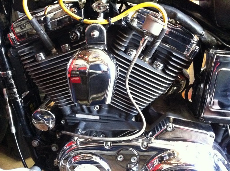
At Oil Pressure Switch
The oil pressure switch is directionally pointed differently on some year models.
For instance, 99-03 cases have the switch pointing down and 04-up is facing forward toward the frame slightly more so. 7)
So you may need to modify the parts list below to suit the positional needs from different year models.
Parts List:
- (1/8”) 90° fitting
- (1/8“) 'street tee' (for the oil pressure switch)
- (1/8”) 1-1/2“ nipple 1/8”)
- (1/8“) pipe coupling
- (1/8”) 45° fitting
- (1/8“) pipe nipple(s)
- Teflon thread tape or thread compound
Thread the 90° fitting into the orifice that the pressure switch came out of first.
Thread in the tee fitting so that one port is facing straight out towards the left of the bike and the other port towards the front of the bike.
Test fit the pressure switch to make sure you have room for it before going any further.
Then apply the thread sealer and install it into the forward facing part of the tee.
Thread the 1-1/2” nipple into the left facing port on the tee (with thread sealer).
Then add the pipe coupler and the 45° fitting onto the coupler.
The 45° fitting should be facing towards the left forward corner of the second cylinder.
Thread the oil line onto the 45° to run to the gauge.
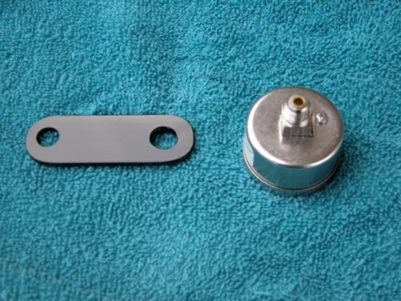
A 1/4“ thick aluminum flat stock can be purchased from a hardware store for the gauge bracket.
Cut off 4” and drill 2 holes on each end.
Round one end and paint it if you like. 8)
 |
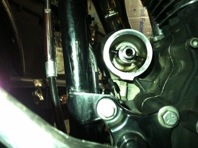
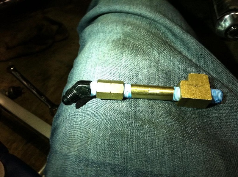
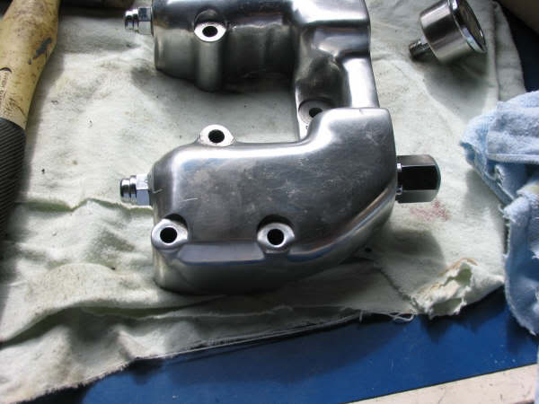
| Remove the oil filter and oil pressure switch. 9) | Install a 90° fitting where the pressure switch was. 10) | The fittings all together and ready to be put in place. (in addition to the first 90° fitting) 11) |
 | 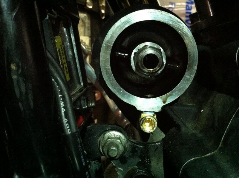 |  |
| 2nd 90° faces down to mount the oil pressure switch. Measure to position the fittings so the switch is clear of the frame and engine case. 12) | ||
 |  |  |
Alternate Fitting Positions at Filter Pad
| This setup has the gauge line on the bottom and switch on top 13) | |
 |  |
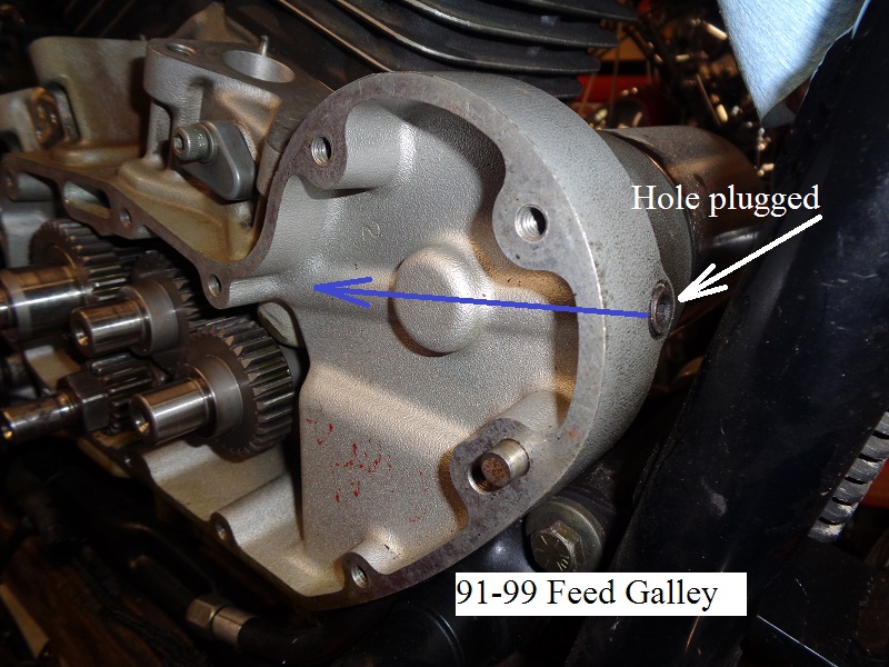
At case plug outside filter (91-up)
This is the rifled hole to connect filtered oil to the right case feed galley.
The plug on the end, as in the pic below, simply plugs off the hole that was required to drill the hole.
Installing a pressure gauge line here is possible.
However, it will measure filtered oil.
The filter media is a restriction which will change the pressure at the gauge based on how much debris is gathered in the media.
It will not be a reflection of how much actual pressure is being sent from the oil pump.
IH
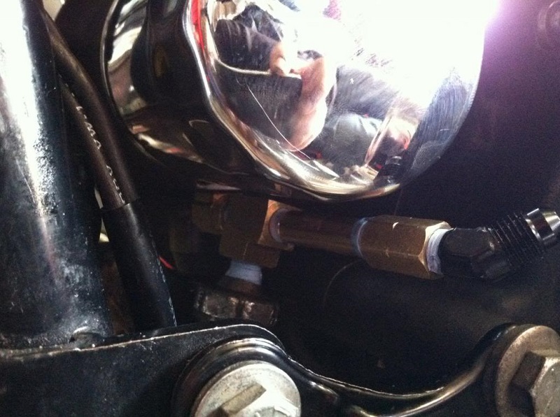
At Oil Pressure Switch at Oil Pump
According to the MoCo (FSMs), the oil pump is the prime testing point of oil pressure to the engine.
The procedure is to take the oil pressure gauge off and install an oil gauge there.
This works if you have verified that you do have oil flow to the engine and just want to check the pressure at the pump.
This takes the oil pressure switch as well as the oil light out of line.
However, as in the pics below, a tee can be added inline for a dedicated gauge.
You can either mount a permanent gauge to the tap or plug it off until needed.
This will keep the switch and the oil light inline and working if you need it.
| Piping added to include the gauge and the oil pressure switch 15) | |
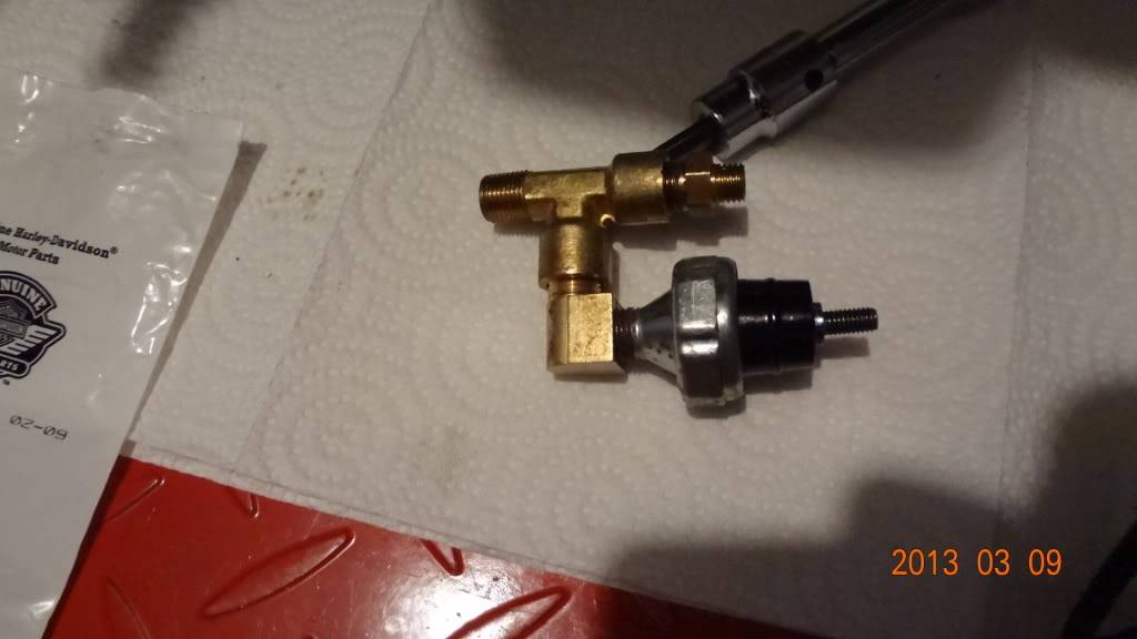 |  |
Remove the oil pressure switch from oil pump and install an 1/8“ hose or tee fitting, then an 1/8” the hose to the oil gauge.
Instead of removing the oil pressure switch out of the oil pressure chain,
You can remove it, install a tee at the pump, fit the switch to one end of the tee and the other end to the gauge.
This will keep the switch, and more importantly, the oil light in the loop.
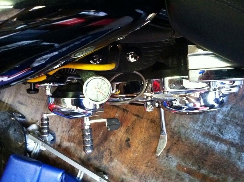
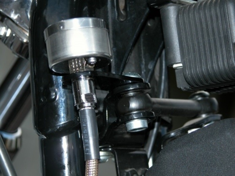
Mount the oil gauge where it can be seen during operation.
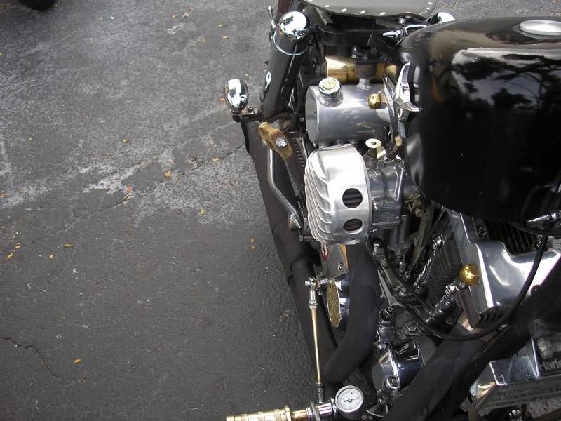
You can use a flexible braided rocker box oil lines and mounted the gauge just off of the forward controls or on the downtube.
| Oil pressure gauge on a 75 model downtube 16) | |
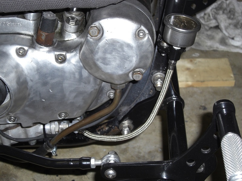 | 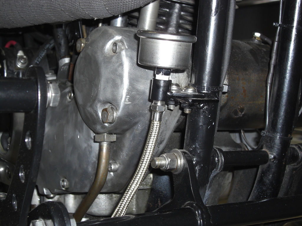 |
| Oil pressure gauge on a 74 model mounted down low by the forward controls 17) | |
 | 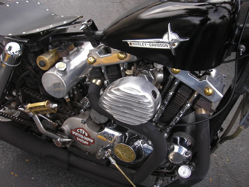 |
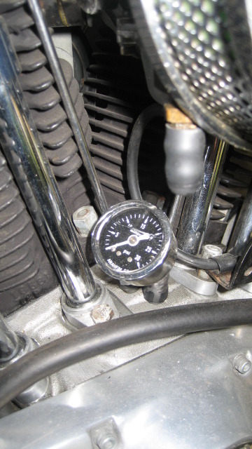
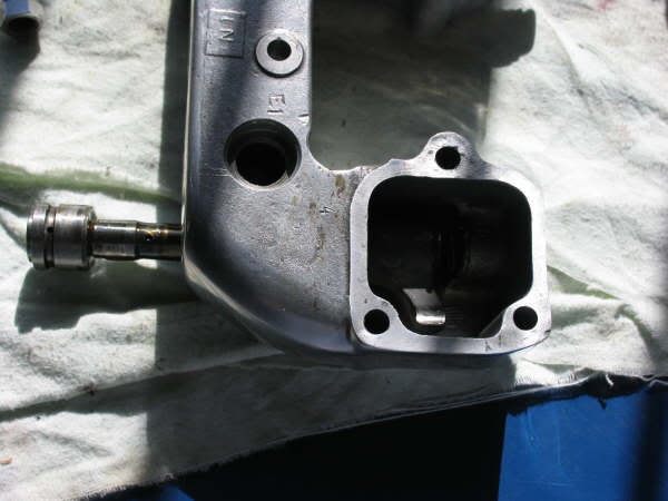
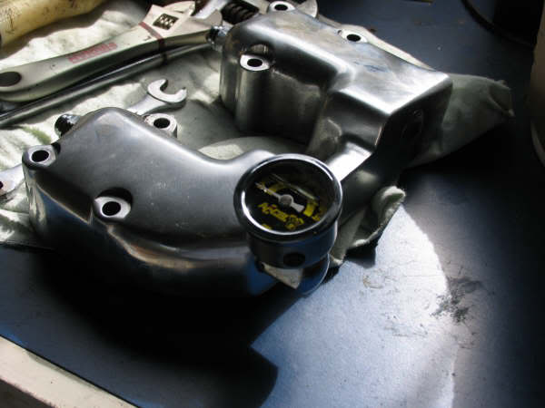
At Plug Between the Tappets
On some models there is a plugged hole between the tappets.
The plug was removed and a gauge was installed to measure pressure inside the case. 18)
 |  |  |
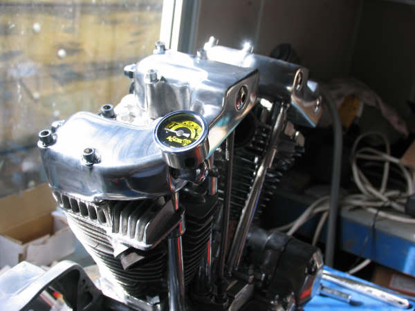
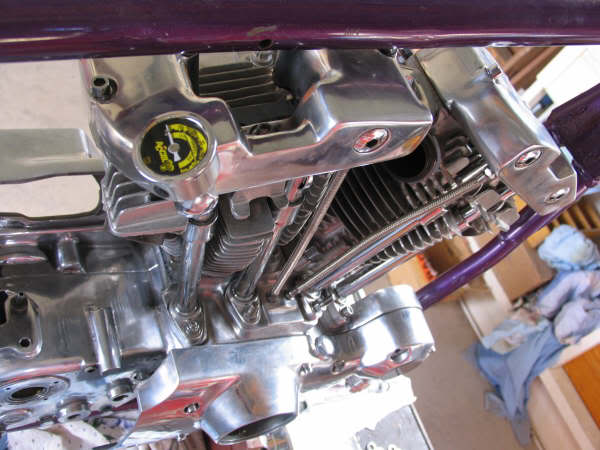
At Rocker Box
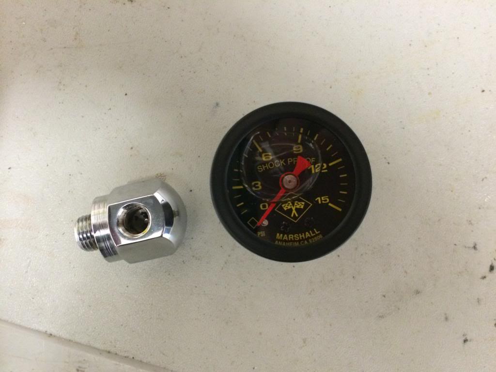
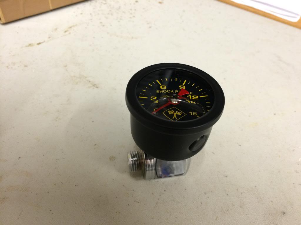
This was done on the rear rocker box of a 77 model Sportster. 19)
With the engine in the bike, simply remove the rocker shaft end plug and screwed in the adapter and the gauge. 20)
There is no need to remove the heads.
Use Foghollow adapter (H80409) or similar.
 21)
21)  22)
22)  23)
23)
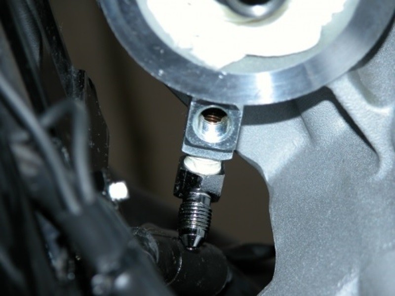
The end plug was removed and replaced with a gauge adaptor. The gauge will be installed there. 24)
 |  |  |
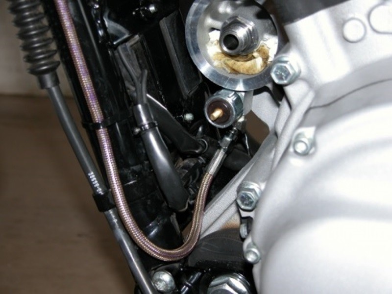
The lubricated shaft was fitted back into the rocker box. Be sure that the spring and spacer washer are in place.
Fit the O-ring and gauge adaptor and lightly screw up by hand. You can use a bit of rubber grease on the O-ring to make it slide into the rocker box nicely.
Fit the aluminum shaft washer and dome nut. You can also put a bit of Permatex silicone on each side of the washer, as this doesn't spin once it tightened up. 25)
 |  |  |
Tighten each side a bit at a time so that you get the gauge mount oil hole in the right spot.
Tightening each side slowly allows the O-ring to slide into the rocker box and not catch on an edge.
Tighten to specs and wipe off the excess Permatex on that one end. Add a bit of liquid thread sealant on the gauge threads.
Make sure the angle of the gauge is good from your sitting position. You can back off the shaft nut and relocated the shaft if needed. 26)
 | |  |
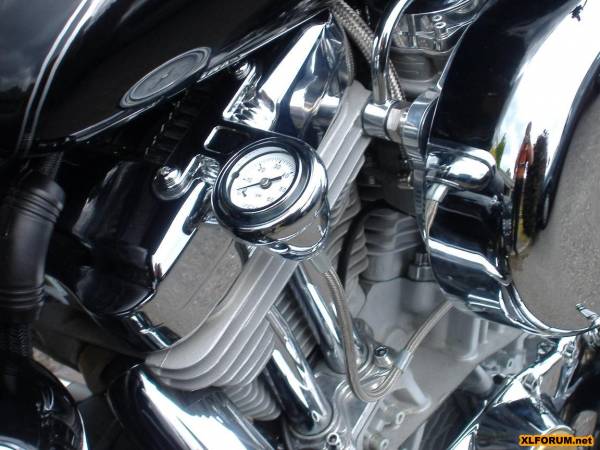
Gauge Mount Locations
| Arlen Ness mounting kit and VDO gauge. 27) | ||
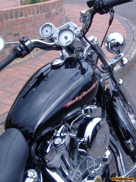 |  | 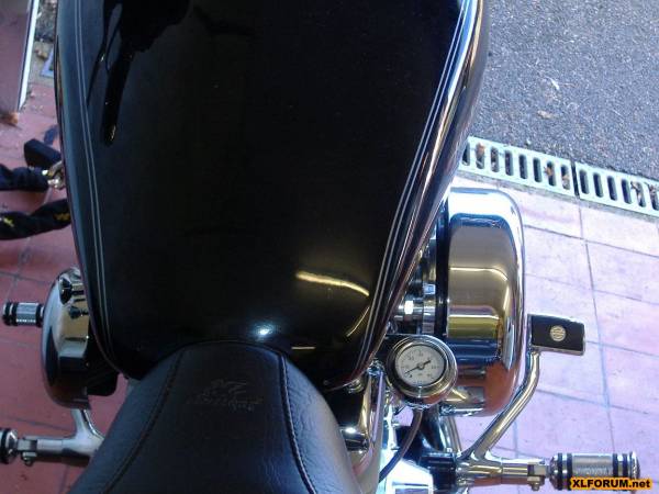 |
| Gauge mounted at the downtube 28) | ||
 |  | 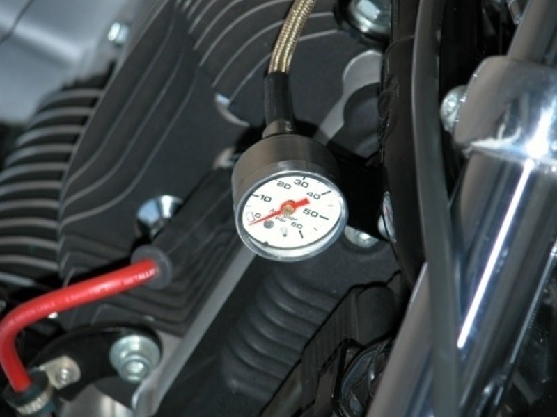 |
| Gauge mounted on the enrichner bracket with an L shaped bracket from an old carb support. 29) |
 |