Table of Contents
This is an old revision of the document!

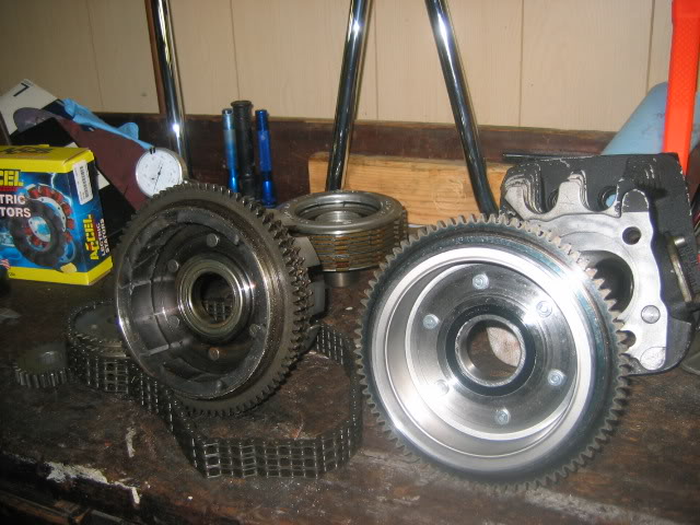
REF: Primary Drive & Clutch
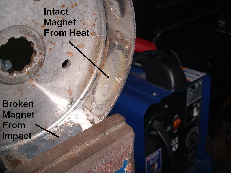
Broken Rotor / Clutch Basket Magnets
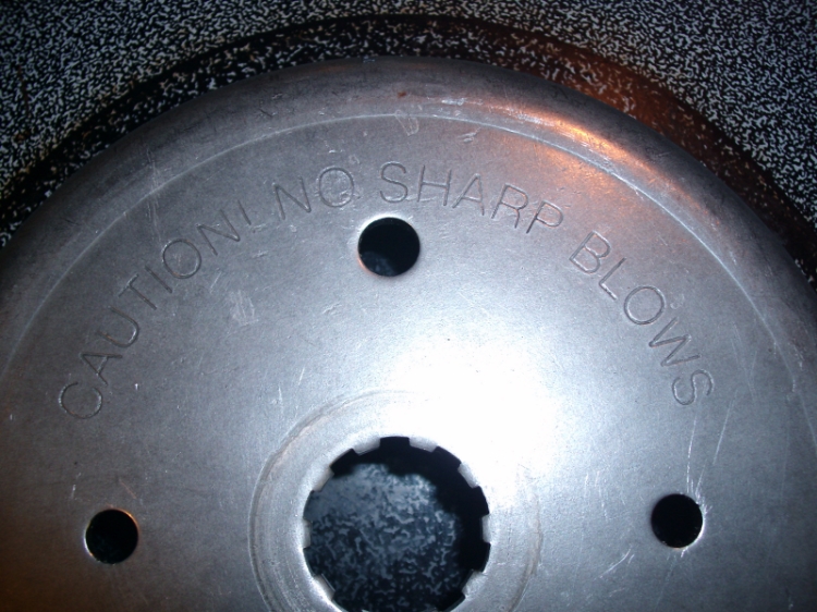
If you look on the rotor of your late Ironhead to present Evo you'll see a warning. It says “Caution No Sharp Blows”. 1)
| This is what can happen when you use a hammer on the clutch basket / engine sprocket rotor (respectively to your year model) 2) |
|
 | 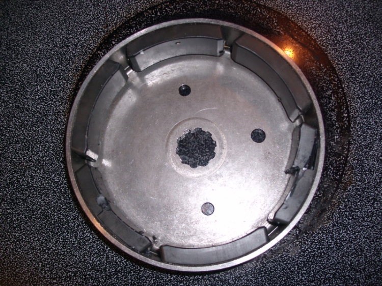 |
This was done on purpose as an illustration. “I started slow and then went a little harder until I heard a couple of the magnets drop out”.
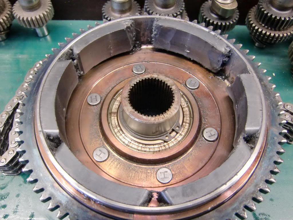
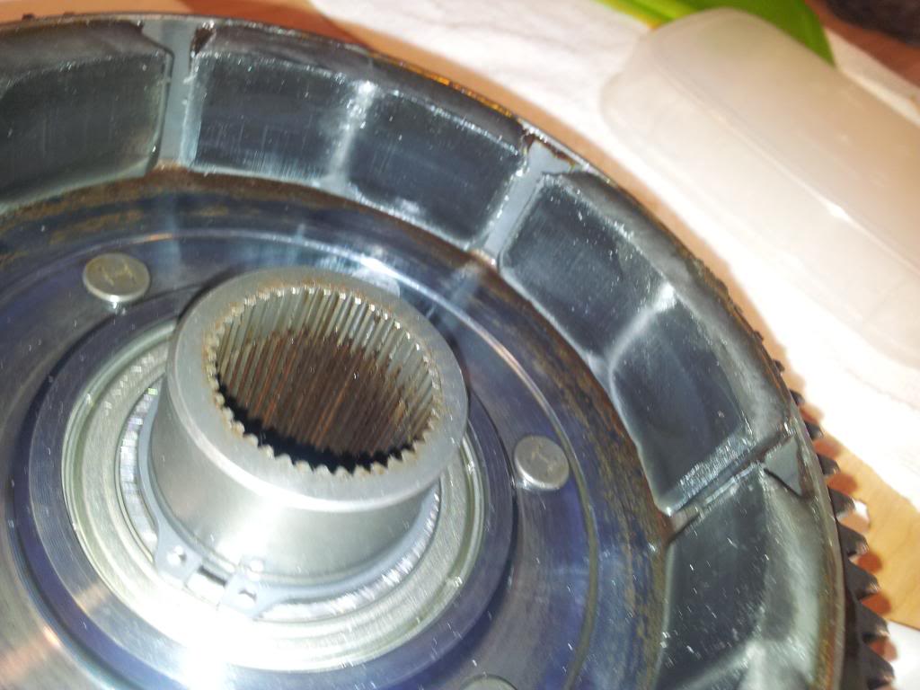
As you can see, two of the magnets broke and then fell out. The surface of the magnet that was glued stayed in contact with the rotor.
Actually the two broken magnets shattered. They're ceramic and will break like glass.3)
Sourcing Replacement Magnets
- There doesn't seem to be a source for new replacement magnets. 4)
- You can check with your local HD to see if they may have a used take-off with donor magnets in the service dept. (that they haven't thrown out yet).
- A good source for replacement donor magnets is a Big Twin six magnet rotor (preferably used), add your best source of heat to remove its magnets. 5)
- DO NOT use a hammer to knock them loose. You might get lucky but it's likely the magnets will break before letting go of the hub.
Repairing the Magnets in the Hub
Removing the Magnets
Caution…. Use eye and skin protection before attempting to remove them.
- You'll need to either use a solvent (paint stripper has been successful) or heat on the hub to remove the magnets.
Using Solvent:
- The MoCo uses a very thin adhesive that may be resistant to paint stripper. 6)
- The idea, however, is that it will soften the epoxy holding the magnets on.
- It may take several applications, but eventually it will soften the adhesive enough to allow the application of heat.
- So, if this doesn't work, you'll need to move on to heating the hub.
- Soak the inside of the hub / rotor with paint stripper (Acetone or other) for about 24 hours.
Using Heat:
Caution… Find some way to handle the hot magnets or metal. whether using channel locks and a large screwdriver, some old oven mits or welding gloves can come in handy too.
Let the magnets cool down on concrete or a wood board but not something metal.
- You do not have to use too much heat, just enough to melt the glue that holds the magnets on.
 |
| It takes awhile but eventually the heat does it's job. 7) |
- A heat gun has been used successfully on the outside of the hub 8) adjacent to each magnet removed.
- A torch (propane or whatever) should work better and faster. However, don't get it too hot or the magnet and the properties thereof could be ruined.
Use a big screwdriver or small pry bar to LIGHTLY PRY the magnets loose or you will break them. TAKE YOUR TIME !!! 9) - You can put it in an oven at 400*, you want to heat it evenly as spot heating can cause distortion. The magnets are brittle so be careful. 10)
- This one was set inside a charcoal grill with charcoal laid in a circle around it. The best way to do this is wait until the rotor has turned color completely.
Then work quickly but carefully. Once the rotor reaches temperature, it begines to turn color rather quickly.11)
(Note: Best to place the charcoal all the way around the rotor so as not to warp it with different temps applied.)
 | 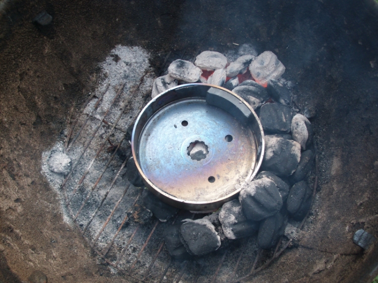 |
| Removing magnets in the charcoal grill 12) | |
Installing the Magnets
- Epoxy that has been used successfully to re-install the magnets:
- JB Weld Tensile strength of 3960 PSI, withstands temps up to 550ºF when fully cured.
- Spacing them out. The magnets need to be evenly spaced apart so as not to throw off the balance of the hub:
- Install them without epoxy, they will all be holding by themselves and against each other if their positions are right. Now calculate the total gap between the two open ends (where there are no magnets), divide the gap by the number of magnets and that will give you the shim (or spacer) thickness. Cut spacers that length and shim them all apart as you glue them in. 14)
- Or, here is a template you can make to evenly space the magnets when re-installing them.
- Fill the gaps between the magnets with epoxy and they probably won't move again. 15)
- Get some clamps to hold those powerful little buggers in while gluing them and watch out for pinched fingers. 16)
- Make sure the magnets are polarized correctly (N/S/N/S/N/S) before you glue them in.
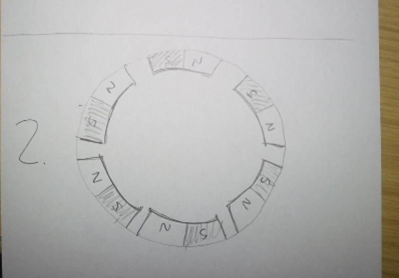 |
| Correct magnet pole positioning 19) |
(L84-90 models)
- With a used clutch housing with good magnets, take all the magnets out first and re-glue them with epoxy (Loctite 3455 used in the pics below).

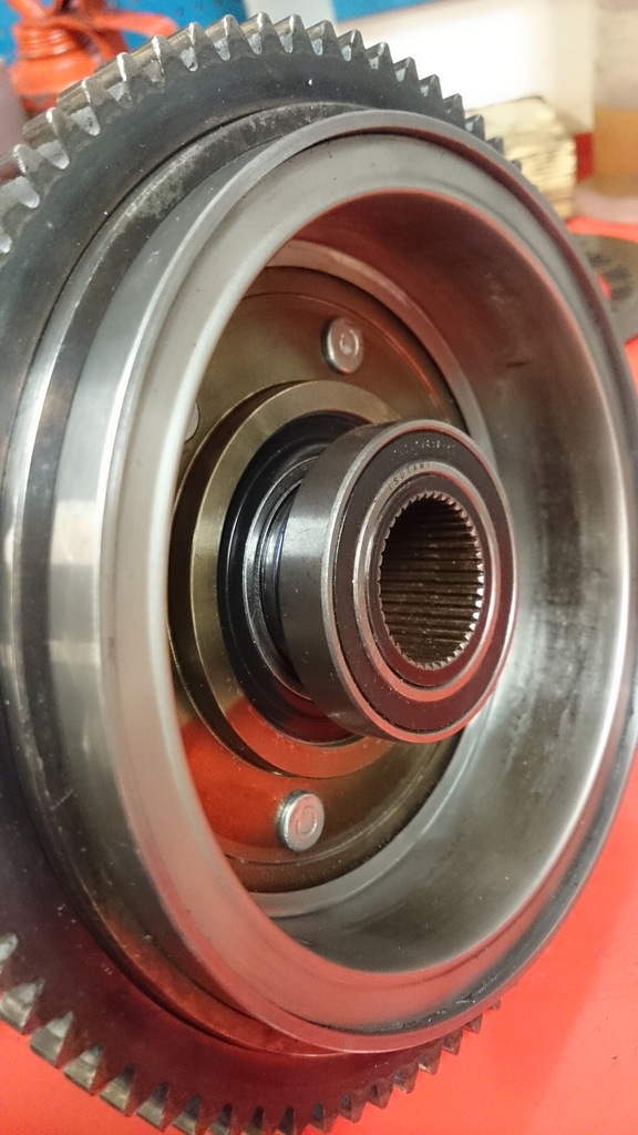
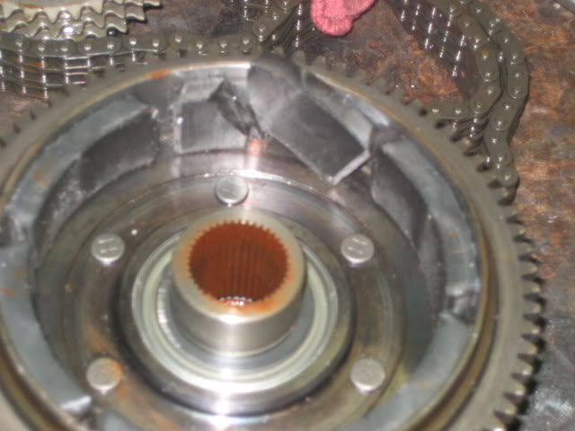
The Dreaded Clutch Basket Wobble (L84-90 models)
- This is a known issue beginning either from a worn out basket or trap door bearing or possibly a worn inner basket spline 22) or maybe a combination of them:
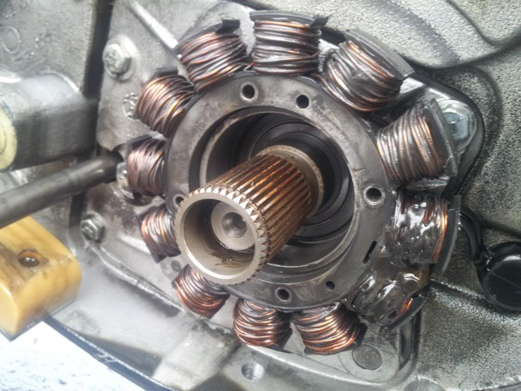
- The late 84-90 sportster has the stator mounted behind the clutch shell, the problem is the stator needs a tight 0.060 clearance to operate right.
- A clutch shell wobbles even when the bearing in the trap door is good, but once it gets worn, it's enough for the magnets to start contacting the stator. Then it's catastrophic for the charging system. 23)
- The grooves in the splines of the clutch basket are a common result of wear. If they get too deep, they can prevent the clutch plates from moving back and forth to engage / disengage. If they're that bad, the only choice is replace the clutch basket. 27)
- If the grooves are minor, just ignore them. On dirt bikes, I have used a straight file to smooth out the high spots, but you have do go all the way around the basket and file down each spline the same amount. This is because you want all the splines on the clutch basket to contact all the tabs on the clutch plate at the same time. If you file down just one spline, none of the other splines / tabs will make contact, and that one will wear very fast.
- This is something that is a bit of a pain to do, and at best it can get a bit more mileage out of the clutch basket. At worst, it can lead to total clutch failure.
Parts Repair
- To replace your exiting hub you'll have to go with an aftermarket as in the V-Twin version since the OEM clutch shell has been obsoleted for parts order by the MoCo.
- To repair your existing hub / rotor and since the magnets are not available for purchase, one idea is to buy a used clutch shell on Ebay.
- You might go even cheaper if you can find one with a few bad magnets to remove the good ones and glue into your existing hub.
- Then get a new stator and trap door bearing.
- However, you haven't solved the problem. It will happen again. 28)
A Solid Repair Solution for L84-90 Clutch Hub
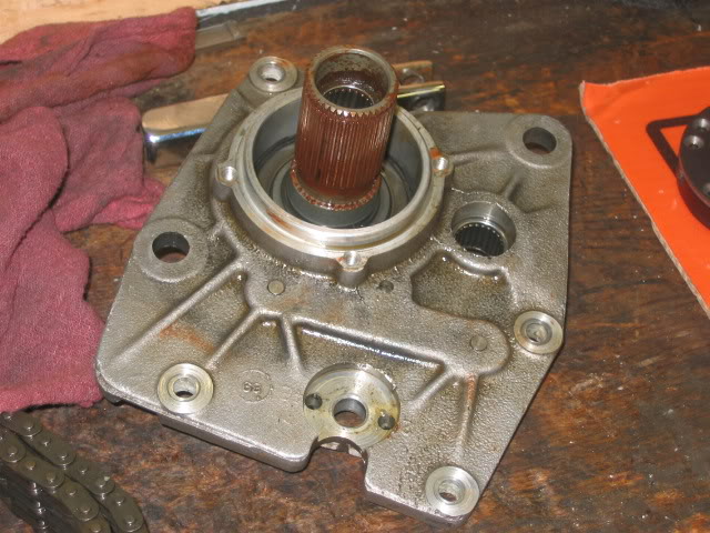
- Replace the trap door with a Zipper's billet aluminum door with a double row bearing.
- The Zipper's trap door (817-840 ) can be used as a heavy duty stock (L84-90) replacement or as a rigid backbone for drag racing and high output 4 speed alternator-equipped Sportsters.
Includes a heavy-duty, double-row mainshaft bearing for extra strength and stability for the clutch and shafts.
The double-row bearing greatly reduces the clutch shell rocking that occurs under power - which leads to damaged alternator rotor magnets and stators when contact between the two is made. It is a direct bolt-on replacement and includes mounting hardware and countershaft bearing. Made in USA. 29)
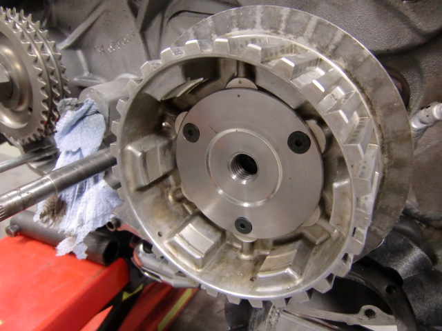
Comparison between OEM and the Zippers trapdoors:
 |  |
| Factory 4-speed trapdoor 30) | |
 |  |
| Zipper's Billet Trapdoor w / double row bearings. 31) | |
- Replace your factory clutch basket with a V-Twin clutch shell with special encapsulated magnets (18-8324 ), new stator, and regulator.
- This is a replica alternator rotor clutch assembly complete with bearing and ring gear, vibration proof magnet construction (magnets are held in place by a stainless steel non-magnetic insert for durability).
Also, rotor clutch assembly has been upgraded to eliminate a common failure of the epoxy breakdown resulting in the magnets to fall out.
This clutch drum features a vibration proof magnet construction with a steel non-magnetic ring to prevent the magnets from falling out.
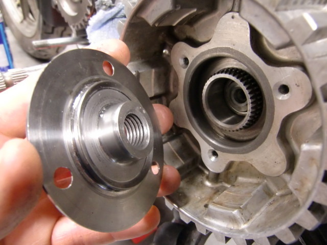
The assembly comes complete with the bearing and ring gear for L84-90 XL models. Replaces OEM (36791-84). 32) - Use your original snap ring when installing. The ears on the aftermarket snap ring are to big and stick out into the hub which then locks up the clutch.
 |
| V-Twin Sealed Magnet Clutch Shell 33) |
- And finally, you can fabricate "The Harton Fix" below (which takes some machining). It can be done on a new or existing hub shaft to add an extra bearing on the shaft and alleviate the pressure exerted on the non-bearing end.
"The Harton Fix" (Late 84-90 Rotor / Clutch Shell Magnets)
Or, “How to fix the dreaded clutch basket wobble” 34) 35)
This is a fix for the famous clutch shell wobble breaking magnets & stator issues on the late 84-85 ironhead and 86-90 evo engines without going to aftermarket products. The V-twin clutch and the zippers trapdoor are nice parts but I don´t think that is where the problem started. The wobble on the clutch gear splines is what I think is the biggest problem to fix in most cases. If the clutch shell can´t wobble, the magnets will not hit the stator and the problem is fixed.
See also Repairing the magnets for your old hub.
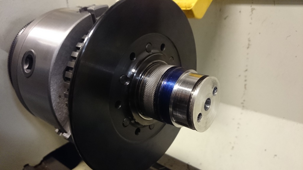
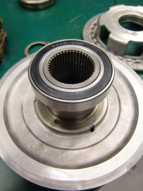
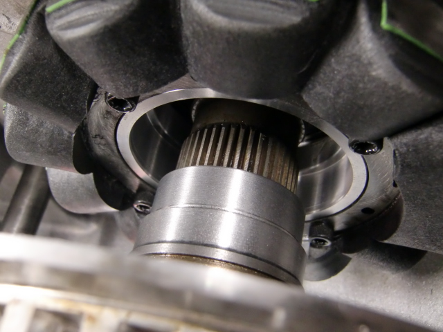
Mount an extra bearing at the back of the clutch
The bearing used in this example is a 6908-2RS ( 40 x 62 x 12mm ) to support the hub and fixed to the gear at the front of the clutch.
This way the clutch will not wobble on the splines.
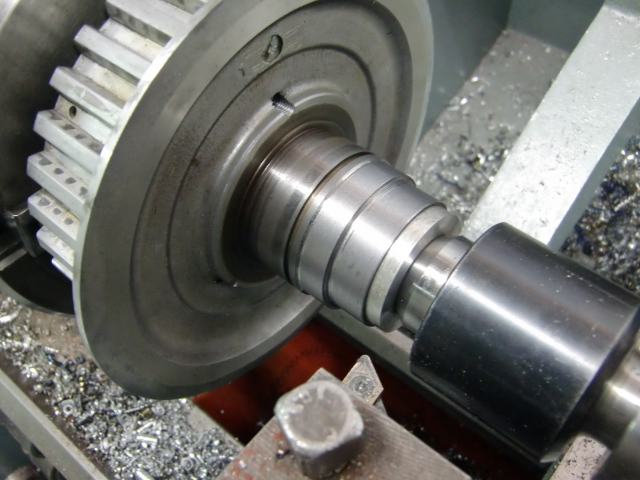
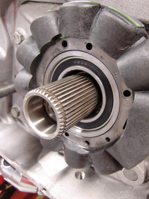
- You'll need to fabricate a sleeve to hold the bearing. The sleeve is for an extra bearing which is mounted to the 'neck' of the clutch hub and it helps when you have worn hub splines. If your splines are good, you can still made that improvement and it will probably help to keep the splines good. 36)

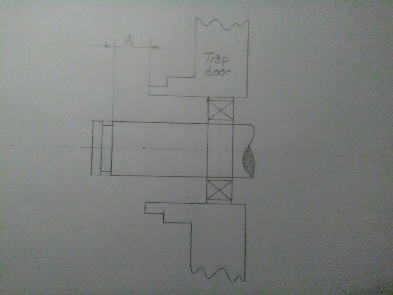
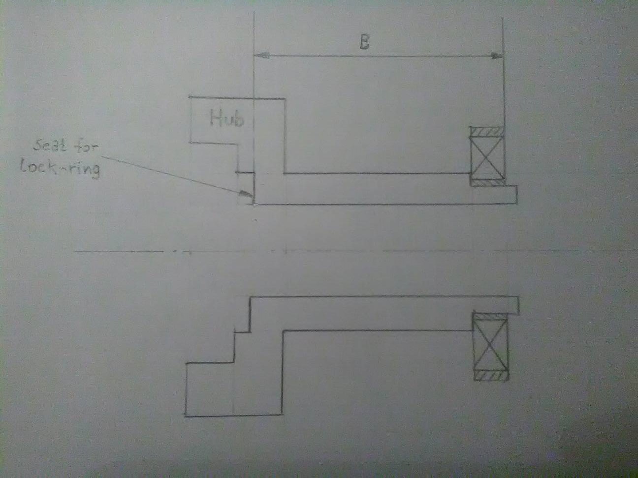
Calculating the sleeve
These dims are for reference comparison only. 39)
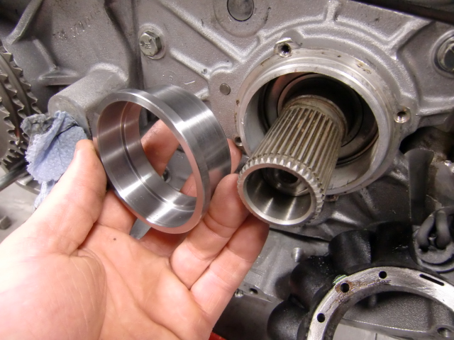
- Find distance A from the groove for the lock-ring to the start of the hole in the trap-door.
- Find distance B from the seat for the lock-ring in the hub to the far side of the bearing.
- Then, distance C = (B + the thickness of the washer under the circlip) - A
- In the image below, the bearing is drawn a little inwards from the end of the hub just to make a point it is the bearing that matters.
However one should try to make it flush with the end. - The distance 5.7mm is to make the sleeves outer protrusion flush with the stator. It can be made longer if needed.
- Ø1 = 70.6 mm (2.780“)
- Ø2 = 62.0 mm make slight press fit for bearing 6908
- Ø3 = 58 mm
- Ø4 = 63.5 mm (2.5”) make it to press fit into the trap-door.
 |  |  |
| App. dims for the bearing race (however, you must do the measuring for Your application). These were taken for an aftermarket hub. These are the updated pics by norseXL 40) |
||