Table of Contents

REF: Service Procedures 10
4 Speed Transmission Removal / Inspection / Installation
This section is not meant to be a replacement to the FSM. It is meant as a compliment to the FSM or added information with pics that are not in the manual. Always buy an FSM and a Parts Catalog to help you along your maintenance path. The Haynes and Clymer brand service manuals for the most part will suffice and they generally have more pics than the HD Service manual. But, end result, there are discrepancies in all of them including the HD parts and service manuals.
Gear Spacing
- Measuring the spacing is tedious. With the trans assembled and fixed in a vice by the bottom edge of the trap door, ensure that none of the parts make contact with the vice while you are turning the gears. Try not to drop the trans on the floor too many times while setting this up To proceed, the trans must be firmly set up so that you can run it thru the gears. 1)
- To measure the gear spacing consistently hold the assembly in such a way that the gears do not move around while you are measuring. You have to press inward lightly on the end of the shafts or on the outermost gear, then ensure that they stay in place while you proceed. Hold the two parts that you are measuring so that they do not move while you are measuring. But do not be too aggressive with this keeping things from moving - you want to simulate what it will be like in a running setup. You do not want to cram them together, just do it enough that every time you do it you will get the same result. 2)
- So you need at least three hands, possibly more, one or two to hold the assembly from moving and changing the spacing while you are working, and another one or two to manage the feeler gauge. It can be done with just two though 3)
- There are only a few options in setting the spacing. I believe that the best you can do is to get somewhere in the range. The shift forks must be in place - one of the options to adjust spacing is to replace the shift forks with different sizes. 4)
Mainshaft
- On the mainshaft, measure between the tips of the dogs on 4th and the face of 2nd; and measure between the face of 3rd and the protrusion from 2nd. 5)
- When setting mainshaft clearances, shims have no effect on fork setting so this can be done in either order 6)
Countershaft
- On the countershaft measure the space between the tips of the dogs on 1st and the face of 3rd; and measure between the face of second and the protrusion from 3rd.
- When setting up clearances on the countershaft, especially if your current shift fork isn't getting you into tolerance and needs to be replaced with a different offset… 7)
- Do the fork spacing 1st, then shim for end play because on the counter shaft there are shims that go on both sides of c-shaft low gear (17t). 8)
- The shims (2 shims on 73> type gear, one on 72< speedo type gear) on left (shaft) side of 17t gear will affect fork spacing. So, you can use them to your advantage with forks. 9)
- When changing them for fork spacing after c-shaft has been shimmed in case will require you to re-shim in case for end play because you have changed the deck height of the c-shaft assembly. 10)
Countershaft and Oiler Plug
- Before installing the oiler plug, set it off to the side until after you've set / checked your final countershaft endplay. otherwise it'll be in your way. 18)
- The oiler plug should be a tight interference fit. It should go in and stay in with the engine running and vibrating and carrying on. Upon dis-assembly, many are found to be loose or rather the hole has probably been worn from the aluminum being smashed in and out of a few times without heating the aluminum trapdoor to expand it. This is why you should ALWAYS heat aluminum engine and gearbox casings, wheel hubs etc, with a propane torch before removing or installing bearings. Doing it cold works once, maybe twice, then the hole is worn out. 19)
- To fix a loose oiler plug, you can take the plug to a machine shop and get them to knurl it. That will increase the diameter by a few thousandths. Then re-install it with Loctite. I would use the red, it is the strongest. But you will then need to use a propane torch to break the Loctite to get it back out. 20)
- You can also peen the hole to retain the oiler. 21)
- Late '84 and up trap door does not include a countershaft oiler plug. When installed in this newer trapdoor in older applications, it may easily hit and scrubb the back of the stator due to being too long. It will either need to be machined down for your clearance measurements or the old style trapdoor must be used. 22)
Mainshaft & Countershaft Needle Bearings & Race
Removal
You should ALWAYS heat aluminum engine and gearbox casings, wheel hubs etc, with a propane torch before removing or installing bearings. Doing it cold works once, maybe twice, then the hole is worn out.27)
- Bearing Race Removal / Installation:
- To remove a badly worn mainshaft bearing race, remove the retainer ring (two thin blade screw drivers, one to get an end lifted/started and the other to get under the ring and work it around, and a lot of patience) 28) and washer. Discard the retainer ring. Heat case surrounding the bearing hole and drift new race inward from the outside of the case. Press new race in until shoulder is against case inner surface. Check specs for correct fit of mainshaft right side roller bearing. Install washer and new retainer ring. 29)
- Countershaft Bearings:
- For the countershaft bearings, select a socket (and extension) that just fits inside where the bearing is seated. Drive old closed end (and new) bearing from right to left with the socket/extension and a hammer using only light blows. The new bearing's max install depth is flush with outside of case (min depth is .030” left outside of case). For the trap door countershaft bearing, carefully remove the oiler plug without damaging the “snout”. Drive bearing out in the same manner with socket against printed end of bearing. Install new bearing 1/16“-3/32” below flush with inside edge of door. 30)
- Clutch Gear Bearing:
- Clutch gear bearing requires removing large snap rings, lightly hammer the clutch gear out with a small piece of wood between hammer and shaft. You can even thread the large nut on so it is on flush with the end of the shaft for support. Then the bearing needs to be pressed off. New bearing gets pressed onto the clutch gear until it is flush to the gear and install it into trap door. 31)
- An alternative for the needle bearing in the clutch gear: Find a washer that's the same size as the bearing and cut two flat places in the edge of the washer so it will pass through the bearing, turn it flat against the inside of the bearing and use a threaded piece of 5/16 rod through the bearing and washer, put nuts on each end of the rod and use a larger socket to pull it into. 32)
Installation
You should ALWAYS heat aluminum engine and gearbox casings, wheel hubs etc, with a propane torch before removing or installing bearings. Doing it cold works once, maybe twice, then the hole is worn out.33)
Hopper
- If you are using a new shaft and race, you will have to line hone or line lap the new race until 23 stock size rollers fit with the correct clearance. Needs to be done in line with the trapdoor bearing. Although someone on here did mention that Jims or someone makes a race that is to size and supposedly does not need line lapping to finish it off. Dunno about that. 34)
- Be sure to put the hardened flat washer BETWEEN the rollers and the spring circlip on the outside, or the rollers and the gap in the circlip will make a big mess of themselves. 35)
- You can assemble the mainshaft into the bearing without the rest of the tranny attached, then put on the sprocket and nut to hold it in place, then slide in the rest of the tranny. I forget which gear (or is it neutral?) to have the tranny in to make this easiest but if you play with it a bit it is fairly obvious which gear lets the mainshaft loose. 36)
trappnman
- You aren't going to be able to put them in place, with the tranny in. Be nice if you could, and it would be nice if HD would have fitted a sealed bearing or anything but those damn loose rollers but such is life….. 37)
- So try to put the rollers in by, as stated, greasing the race, then one by one putting them in place- adding more grease if needed to hold in place. 38)
- That last roller, will be a tight fit, but you should get it into place. If not, and only after a good hearted effort, go to honing. If needed its going to take a VERY little, so careful as you go. 39)
- As far as oversized rollers- you should have that information from wherever you purchased them from the invoice- if you didn't specify size, they would, I'd think be standard 40)
- A tip on putting tranny back through rollers (and unless you are a lucky pup, it might take a few tries, so all you can do is curse, and redo the rollers. to make it easier, make it a 2 man job, with one on one side sliding tranny into case- the other with a awl into the shaft hole on the other end to guide it straight. amazing how much easier it goes. 41)
brucstoudt
- Actually you can put the 23 mainshaft roller's in with the transmission in from the outside. The outer snap ring must be removed, and then reinstalled, after the roller's are in. I prefer to do it this way. I can SEE that they're all in place. 42)
- The outer retaining ring is not a snap ring with hole's for plier's that would make it so simple. It's the circlip type with slot's for prying.
- It's not bad coming out but going back in is tougher. I don't reuse them but I guess it surely wouldn't be the first time.
- Put the roller's at the bottom of the race in first [push up on shaft, slightly]. The end of the mainshaft sag's slightly with no support so if you try to put them in last, it will be tough.
Clearancing Rollers
- Any bearing using loose rollers or balls needs to have a gap left equivalent to about one roller or ball so the rollers/balls do not grind on each other. Check your workshop manual for proper number of rollers.
- If they are still tight, you will have to lap or hone a tiny bit out of the race to give the clearance specified in the workshop manual. I don't remember the exact figure but maybe somewhere about half to one- thousandth max.
- Don't run the bearing with zero clearance. It leaves no room for lubricant between rollers and race/shaft.
- Don't run the rollers crowded so they are jammed up to one another. They will not rotate correctly and will chew the living crap out of the race and shaft.
- Make sure you have that hardened flat steel washer between the spring circlip and the mainshaft rollers, otherwise the gap in the circlip chews up the rollers quicktime. 43)
Mainshaft Needle Bearings
- The standard size for the 23 loose mainshaft rollers is .1562“ 44).
- Question: When does fitting oversize rollers result in MORE running clearance? 45)
- Answer: when the same quantity of oversize rollers are fitted to a 'cageless full compliment bearing'. 46)
- Below are two true geometric constructions of 23 rollers. 47)
![]() 50)
Factory size of:
Main Race is 1.305 dia.51)
Mainshaft is .99152)
50)
Factory size of:
Main Race is 1.305 dia.51)
Mainshaft is .99152)
1957-Early 1982 Mainshaft Thrust Washer Roll Pin
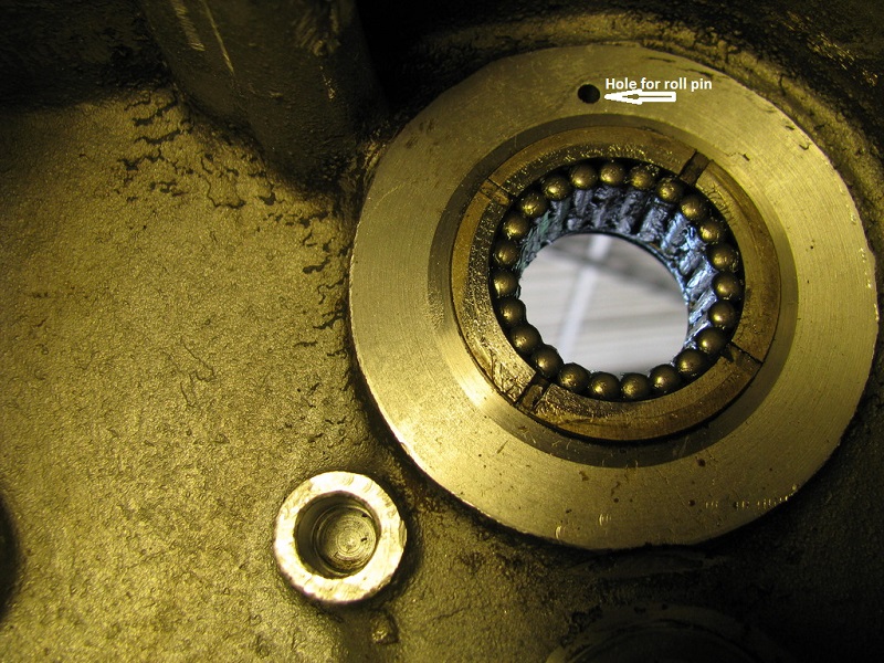
A roll pin is installed at the twelve o'clock position over the mainshaft hole to keep the spacers from spinning. The spacers on the end of the mainshaft have a tab that would hit the roll pin and lock in. If your mainshaft thrust washer has a tab, then it needs the roll pin. Otherwise it acts like an oil slinger, and them parts need that oil! Make sure to put the special hardened washer between the snap ring and the loose rollers.
- Roll pin from 1957 - Early 1982 #(600) and is 1/8” dia x 9/16“ long. It sticks out 3/16” +/- 1/32“ from the alum surface. 54)
- Always replace with a new roll pin, use a good thread lock when installing it. 55)
- NOTE: The mainshaft rollers are NOT lubricated by splash via the static ear washer. There is a curved oil collector on top of the mainshaft bearing that fills with oil being thrown around. The oil is then fed by gravity to the outside of the roller outer race via a hole located between outer case and the mainshaft oil seal. Then oil exits by gravity via the static ear washer. So, oil would still find its way out if it was spinning which questions the static bit of the logic of using the pin. I have run engines with and without the pin, doesn't seem to make much difference. 56)
Removing a sheared off roll pin
- Instead of removing the old one that is sheared off and flush with the case, drill another hole with a drill bit .003” under the pin diameter a few degrees around the bearing on the same radius as the existing pin. Press fit the new pin into the hole. You may want to try this using a scrap piece of metal to determine what size drill bit works best. Your object is to press the pin into a hole so tight that you cannot (easily) pull it out. When you find the correct size drill bit, put a drop of epoxy on the end of the pin then press it into the hole. You don't want loose pins dropping into the transmission. 57) A new pin (about ~ 1 o'clock) next to the old one.58)
- Hand drilling a straight hole is a bit difficult but what I would do is get a piece of wood and drill a straight hole through that using the bit you are going to drill the case with. Make the wood thickness such that the drill extended through it sticks out the same depth you want to drill. Then place the block of wood against the case and this will guide the bit into the aluminum fairly straight and to the correct depth all in one shot. 59) If the hole isn't dead straight it's not much of a problem. If the hole is over size that's not cool. Drill 3/32“ first. Then follow with 1/8”. This will help keep the hole size good. Don't drill thru. If you didn't drill deep enough, you can grind some length off the pin after installation. 60)
- After drilling, you might want to check on the outside of the case to see if a pilot hole came through.
- Another option is to drill through the pin hole to the outside of the case. Drill the pilot to just under the pin size and drift it out. The hole can be plugged with a machine screw. Also, there is no reason a longer machine screw could act as the stop. There is no loading on the pin so it would not take much to stop the rotation. The only drawback is it will probably fall on the shaft seal flange, but the screw can be applied on the outside of the flange or the flange drilled to allow the head to protrude. If this method is considered, use a allen head screw that is hardened as a regular machine screw is on the soft side. 61)
- Another option when drilling to the outside is to fill the outer access hole with good 'ol JB weld once a new roll pin is installed. 62)
Mainshaft Endplay
- The mainshaft bearing in the trap door slides back and forth between the snap rings. 63)
- When checking mainshaft endplay, you need to hold the bearing in the correct position for your clutch style. There are 3 clutch release styles: 64)
- Early dry clutch pushes from the right
- Middle wet clutch pushes from the left
- Late wet clutch pulls from the left.
- If the endplay is set without this in mind all of the clutch release pressure will go against the mainshaft trust washer and turn it blue. The end play you measure will open up when the clutch release moves the trap door bearing over and may cause shifting problems. 65)
- Trap door bearing position should also be set when shimming the trans and setting shift fork offsets. 66)
- You want the pressure on the whole clutch assembly pushing in on it. 67)
Countershaft Endplay
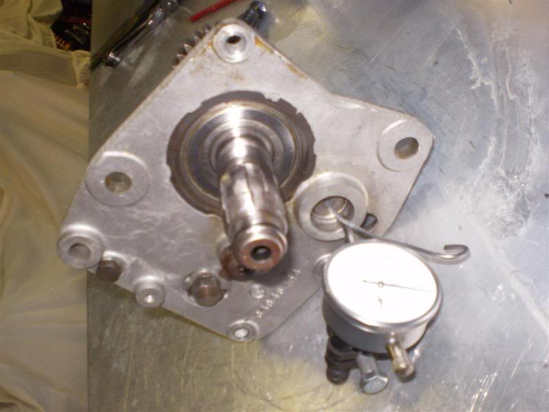 | 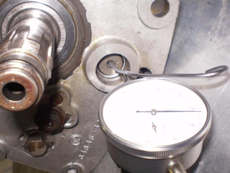 | 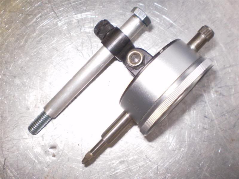 |
| Mock setup: obviously the box is not in the cases where it needs to be to do the job. But easier for pictures. NOTE ! You may be able to see the dial indicator stem is actually sitting on the countershaft bearing outer race - it needs to be sitting on the end of the shaft here, not on the bearing. 68) | A closer shot and here you can see the wire (bent) that is used to push and pull on the countershaft. The dial indicator is centered on zero of course before you start pushing and pulling. You can then read the endplay directly from the dial indicator. 69) | This is the dial indicator mounted on the alloy spacer with the bolt through it. The bolt just screws into the bottom tranny case mount hole on the left case half with the tranny sitting correctly in the engine. You will also need a selection of thrust washers to actually adjust the endplay to get it where it needs to be. 70) |
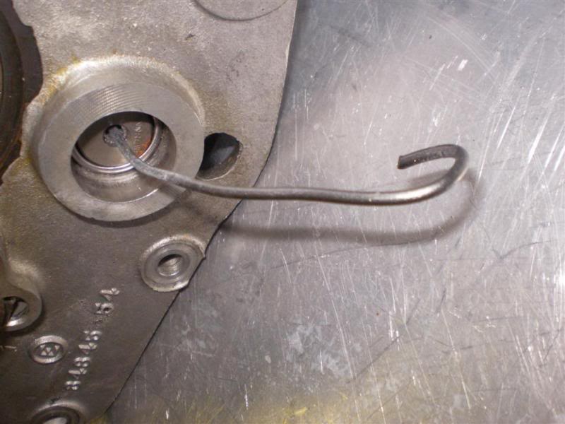 |
| The really important bit - the bent wire. 71) |