Table of Contents
This is an old revision of the document!

REF: Tools - 103
Crankshaft / Flywheel Tools
Removing Flywheels from Engine Case
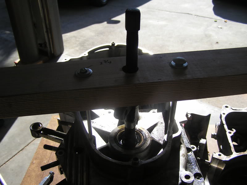 |
| Homemade Flywheel Press 1) |
|---|
Disassembly & Assembly of Crankshaft / Flywheels
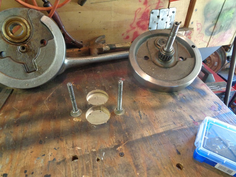
Wooden table as a fixture
3/4“ piece of plywood hinged to the wall with a 2×4 stood up under it for a table / jig. 2)
No measuring of the holes was done but rather the holes were just 'found' as needed.
A 2” hole saw was used to make two bores in the wood for the pinion shaft and then the crank pin.
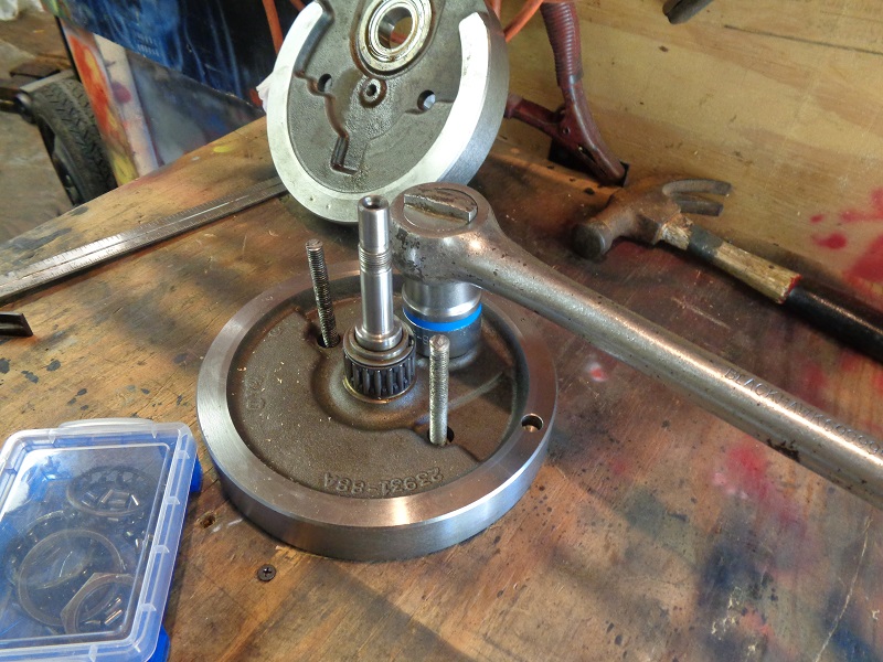
2 lengths of 3/8”x12“ all-thread was fastened to the board as holding pins for the wheels.
The length allows you to raise and lower the all-thread as needed. 3)
See the full disassembly Here in the Sportsterpedia.
 |  |
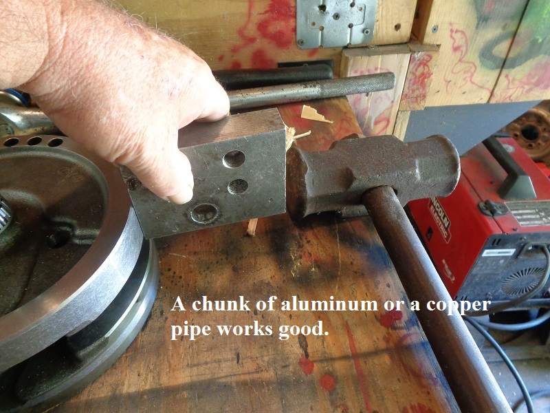
A block of aluminum and a sledge hammer works for knocking the flywheel loose.
 |  |
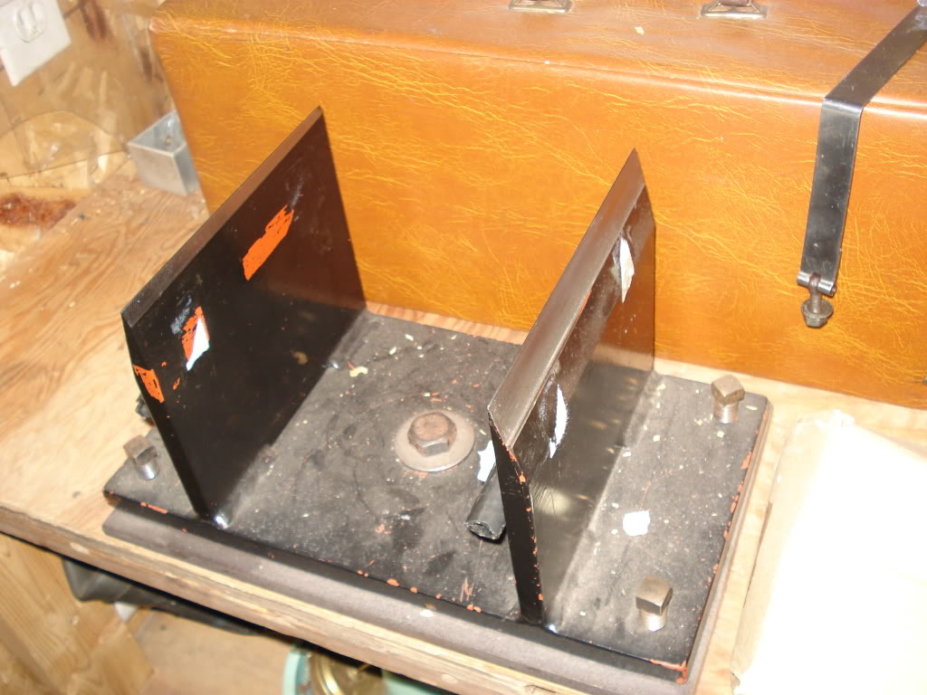
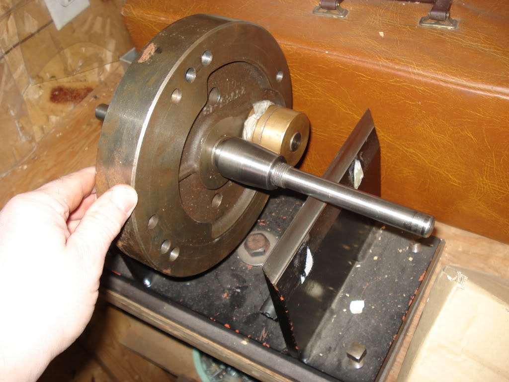
Steel table as a fixture
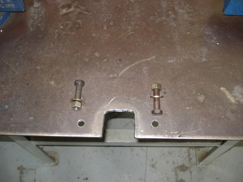

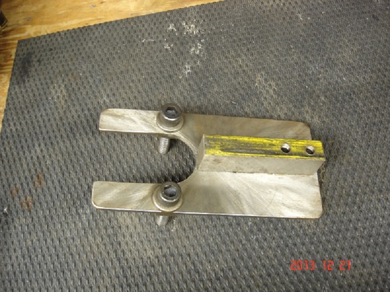
Steel angle fixture

Jig inserts
photos by Iron73 of the XLFORUM 6)
 |  |  |
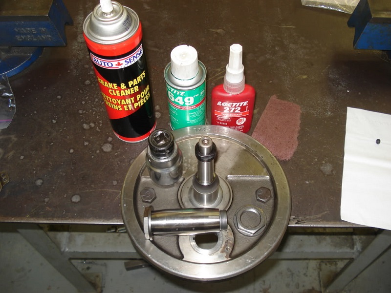
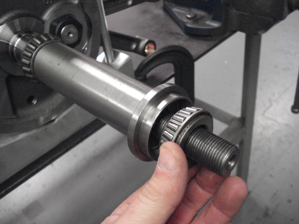
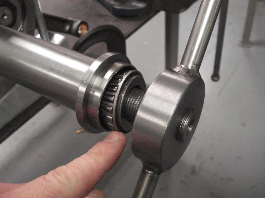
Installing / Removing Timken Bearings
 |  |  |
 |  |  |
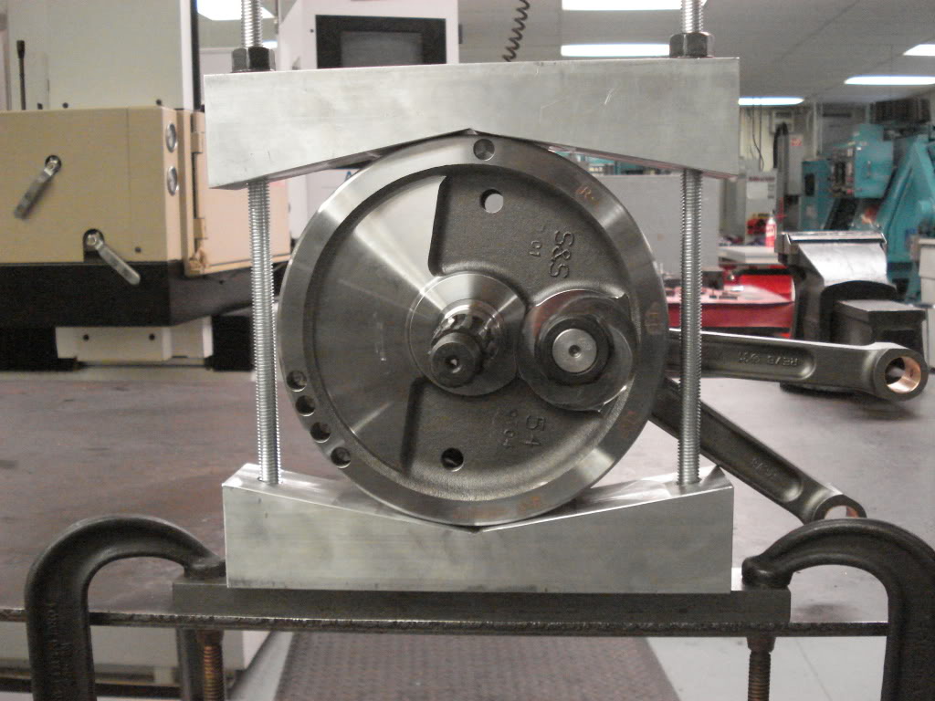
| Crankshaft Jig for Installing Timkens 7) | ||
|---|---|---|
 |  | 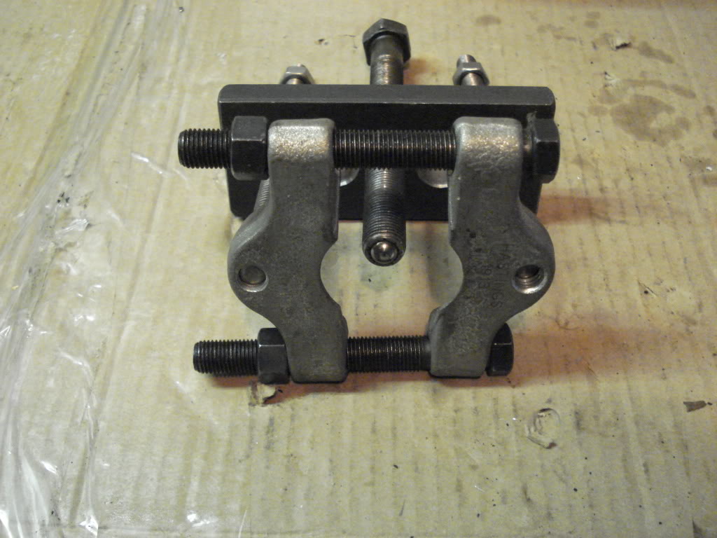 |
| Tool for removal of Timken Bearings 8) | ||
|---|---|---|
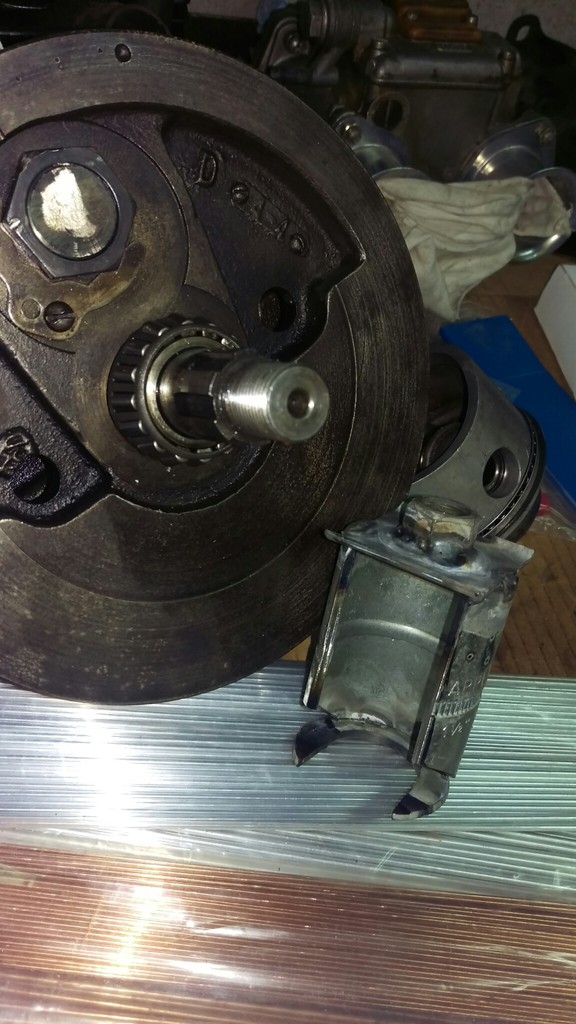 |  |  |
| Homemade Timken Bearing Removal Tool 9) | ||
|---|---|---|
 |  |
| Gear Puller Mod for Removing Timken Bearings. (L)-before, (R)-after 10) | |
|---|---|
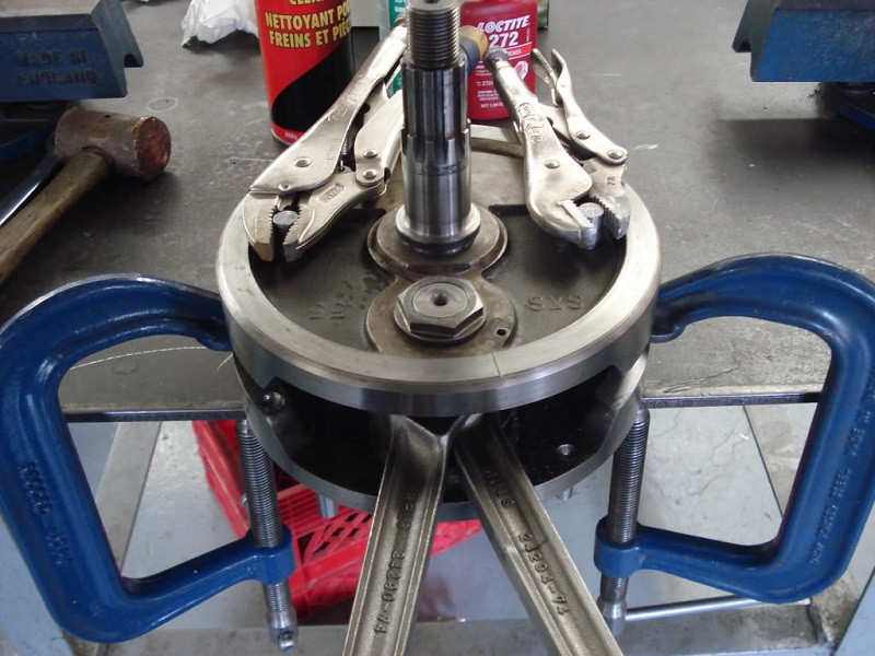
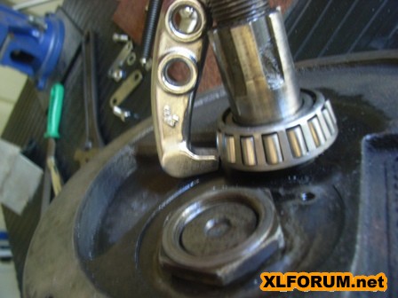
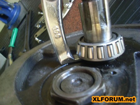
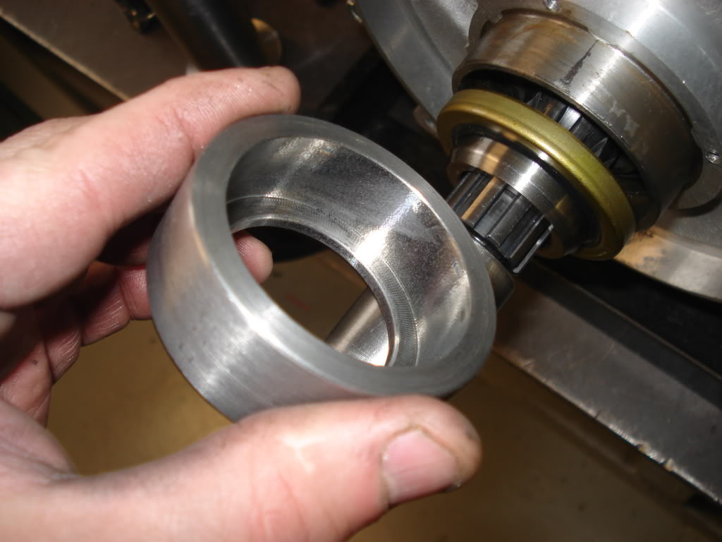
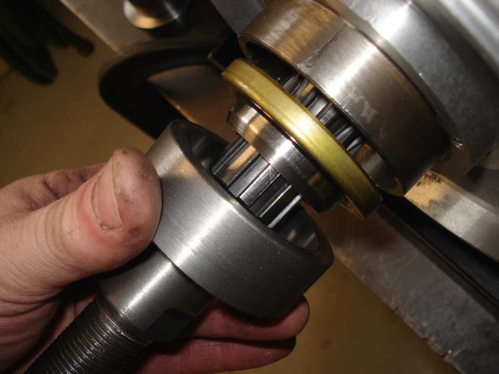
Pulling the Race
Cut the head off of a C-clamp and welded on locking tabs. Huck of tubing from the scrap-bin sliced lengthwise, slotted for the locking tabs
with a cut and ground 1” Hilti bolt washer welded to one end. Another hunk of refuse tubing with set-screws as a sleeve to hold it all together.
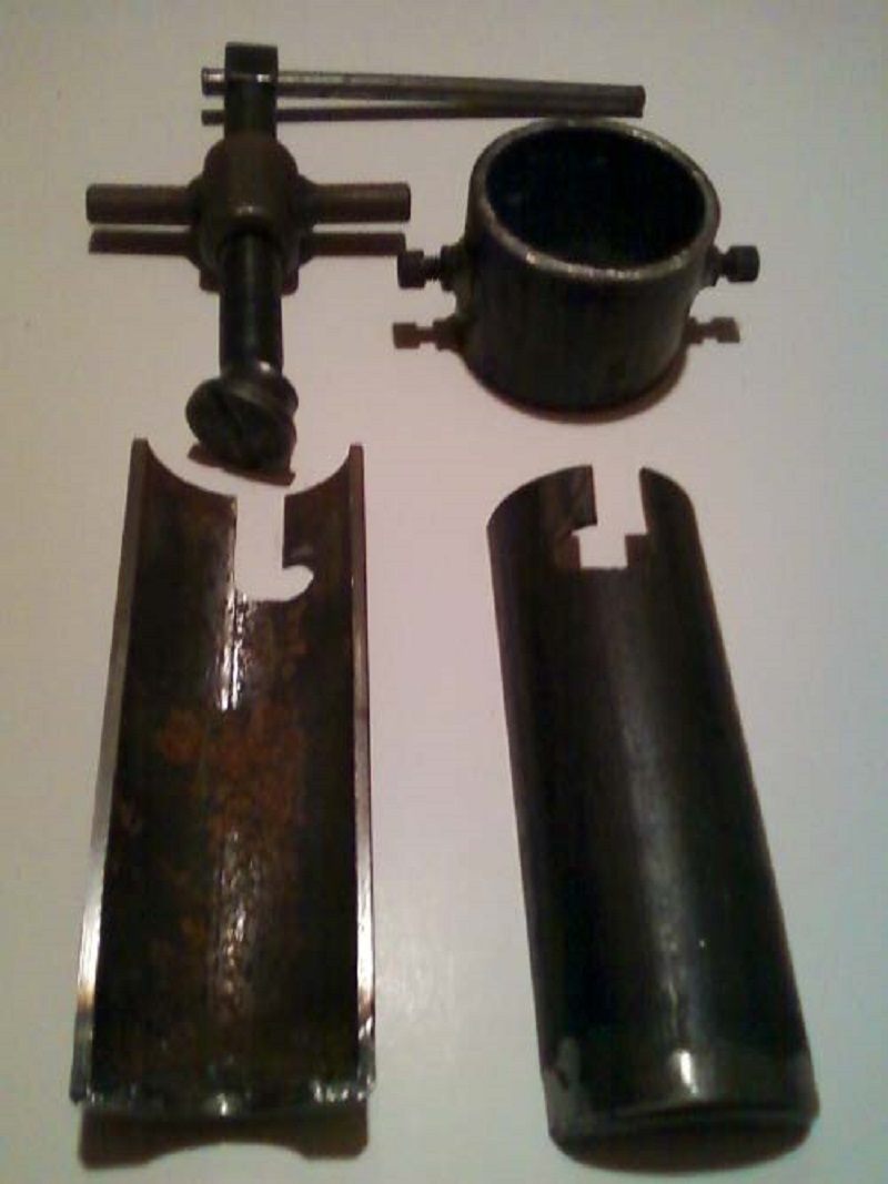 |
| Flywheel Race Puller 11) |
|---|
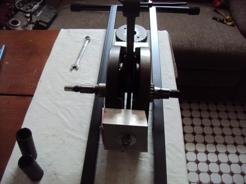
Flywheel / Crankshaft Balancing - Truing
 |  |  |
| Flywheel Balancing Stands 12) | ||
|---|---|---|
 |  |  |
| Flywheel Balancing Tools 13) | ||
|---|---|---|
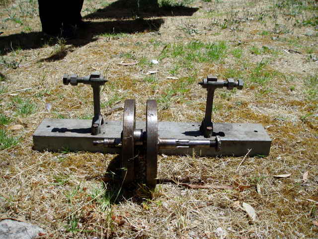 | 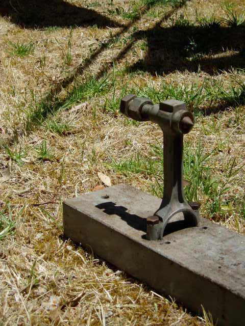 | 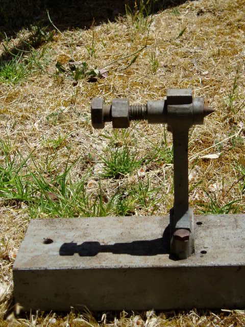 |
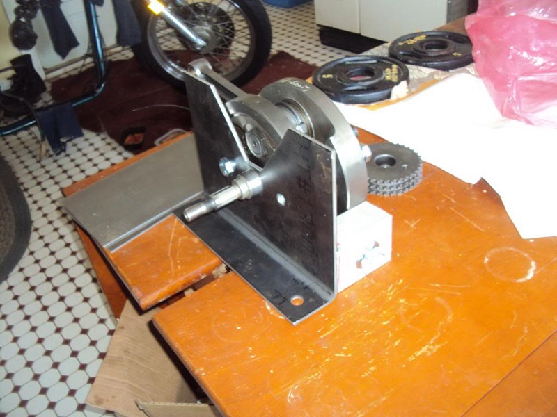
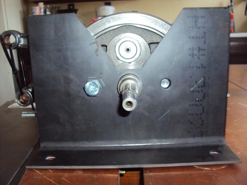
| * A piece of 4“ steel channel as a base. * Two automobile connecting rods are then bolted to holes drilled in it at the right distance apart to suit whatever flywheels are being worked on. * A threaded insert was machined up so a half-inch or so bolt could be threaded threaded through, with locknuts to hold it in position. * The ends of the bolts are machined to a point same as a lathe center (60 degrees maybe?). * A magnetic dial gauge is stuck to the base to suit the job at hand. * This rig has been used to do countless numbers of 45 Flathead bottom ends, J models and big Brit singles like the Matchless wheels in the pic. * The alignment of the two center bolts is not super critical (they just provide the two points). The flywheels and shafts are a straight line between them. |
||
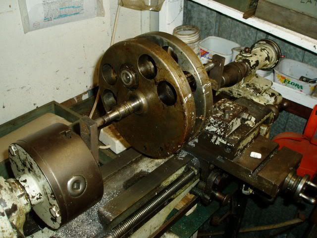
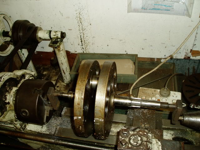
| Flywheel / Crankshaft Balancing and Truing Stand 14) | ||
|---|---|---|
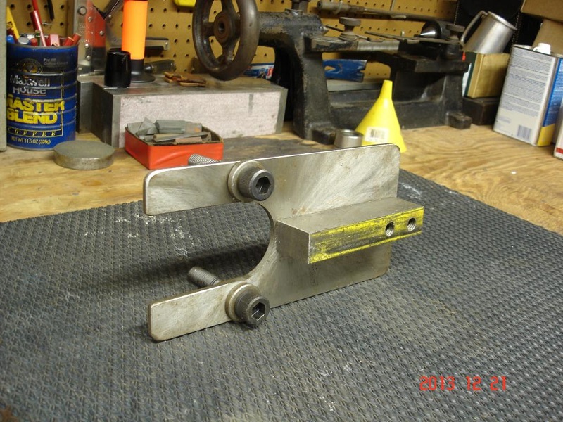
| Here is a pair of adaptors to swing big fat Harley 15) flywheels in a small lathe like a 4.5” swing Myford etc. |
 |
 | 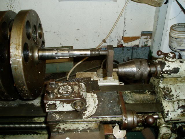 |  |
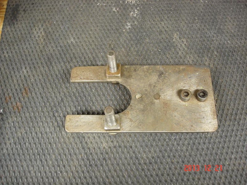
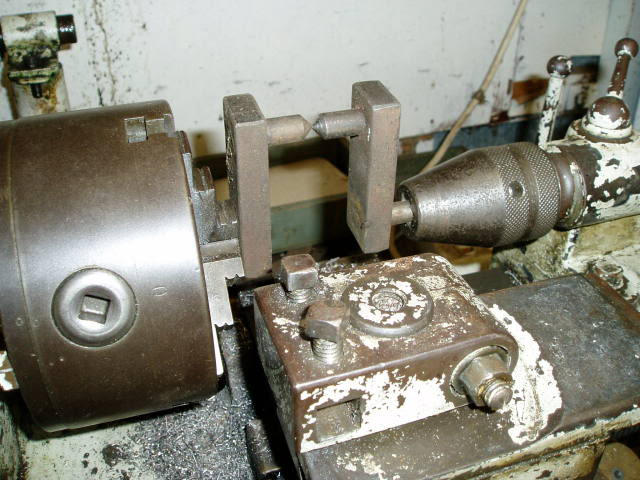
| Here is another way to true flywheels in a small Myford lathe that has only a 4.5“ swing that won't fit Harley flywheels. Two offset pieces made from some flat half-inch thick bar and some half-inch round bar. |
||
| Truing flywheels on center in a lathe via offset jigs 16) | ||
|---|---|---|
Crankshaft / Flywheel Installation
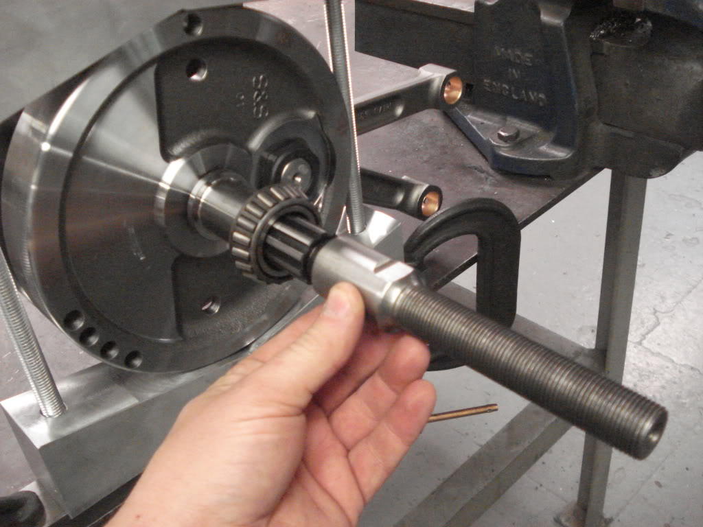
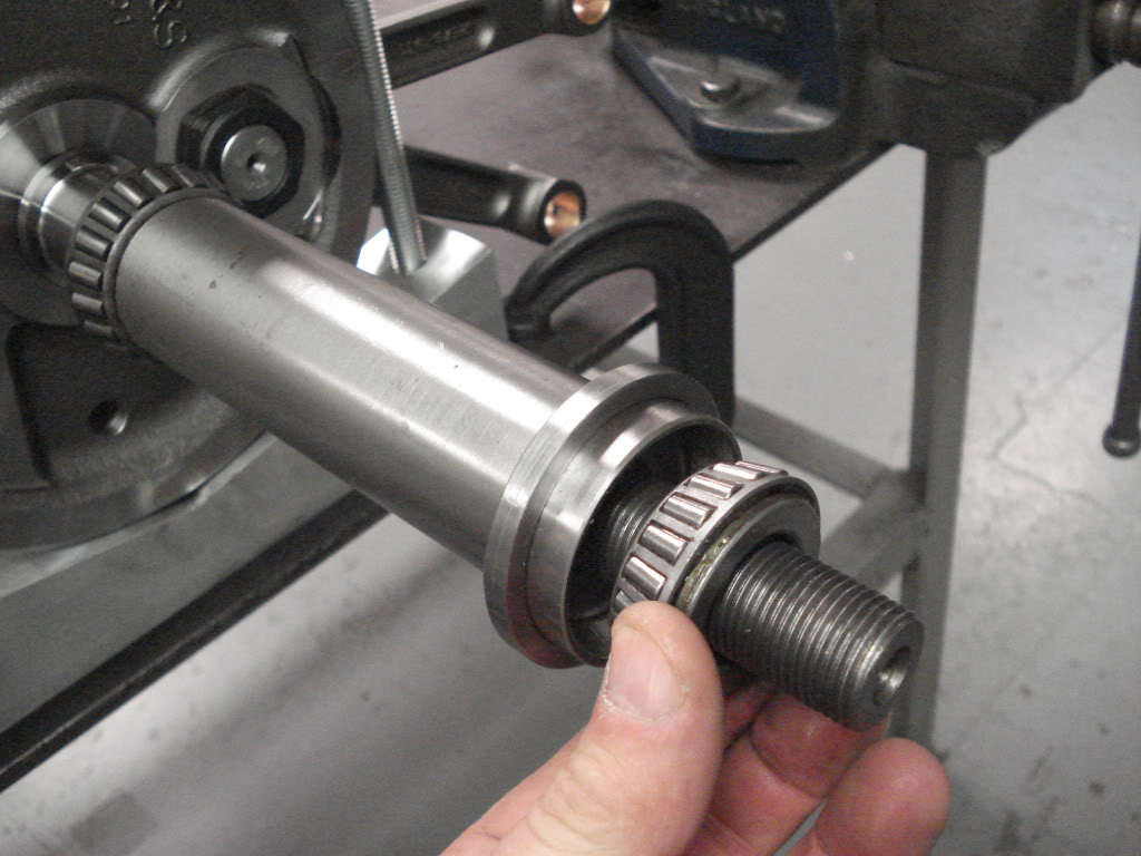
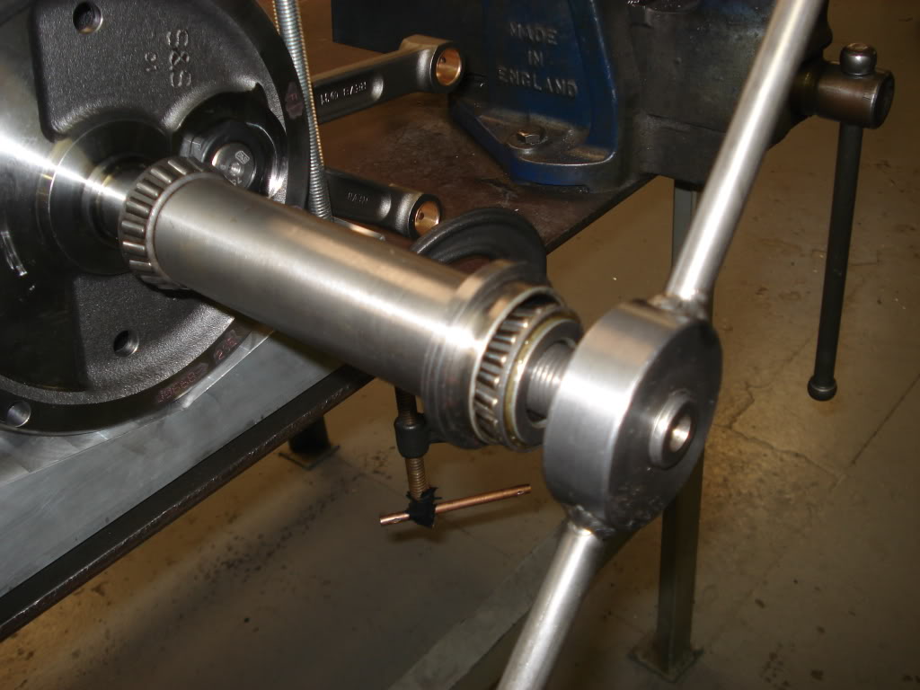
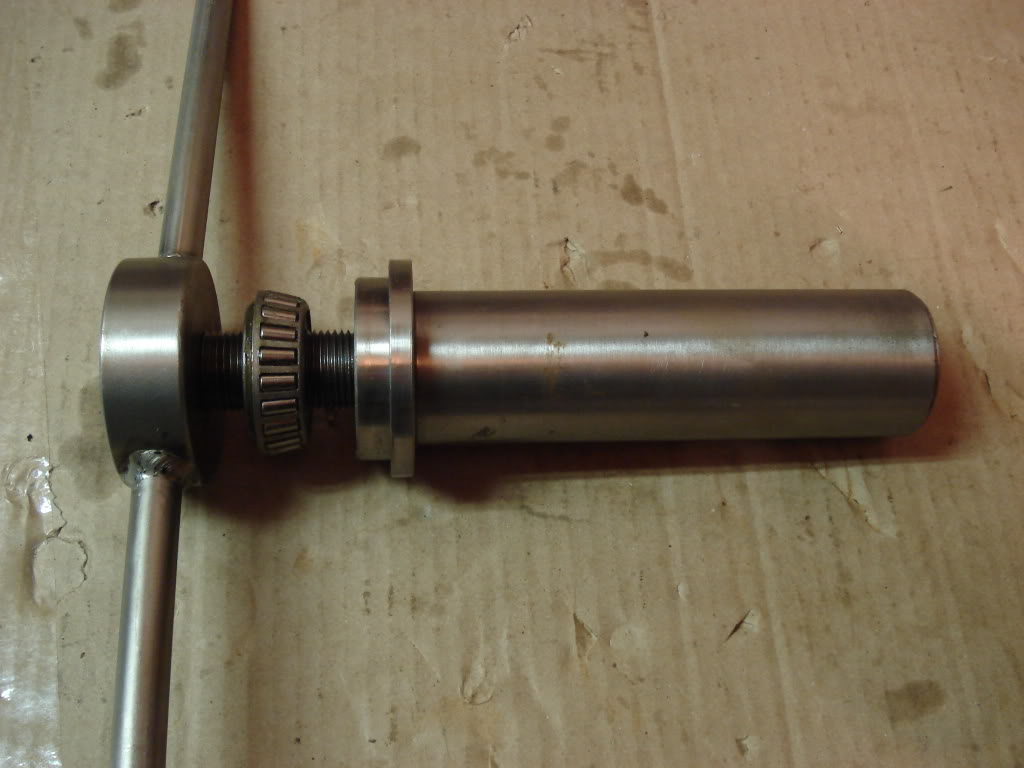
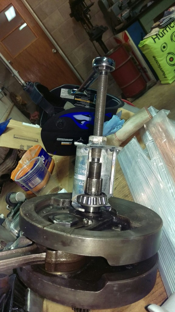
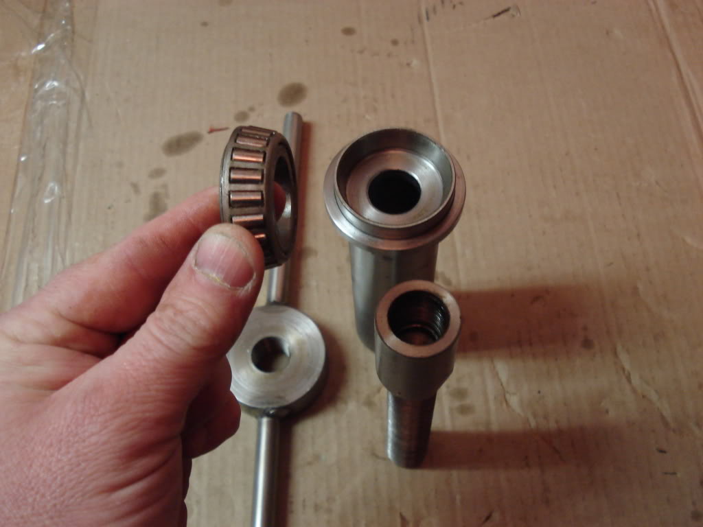
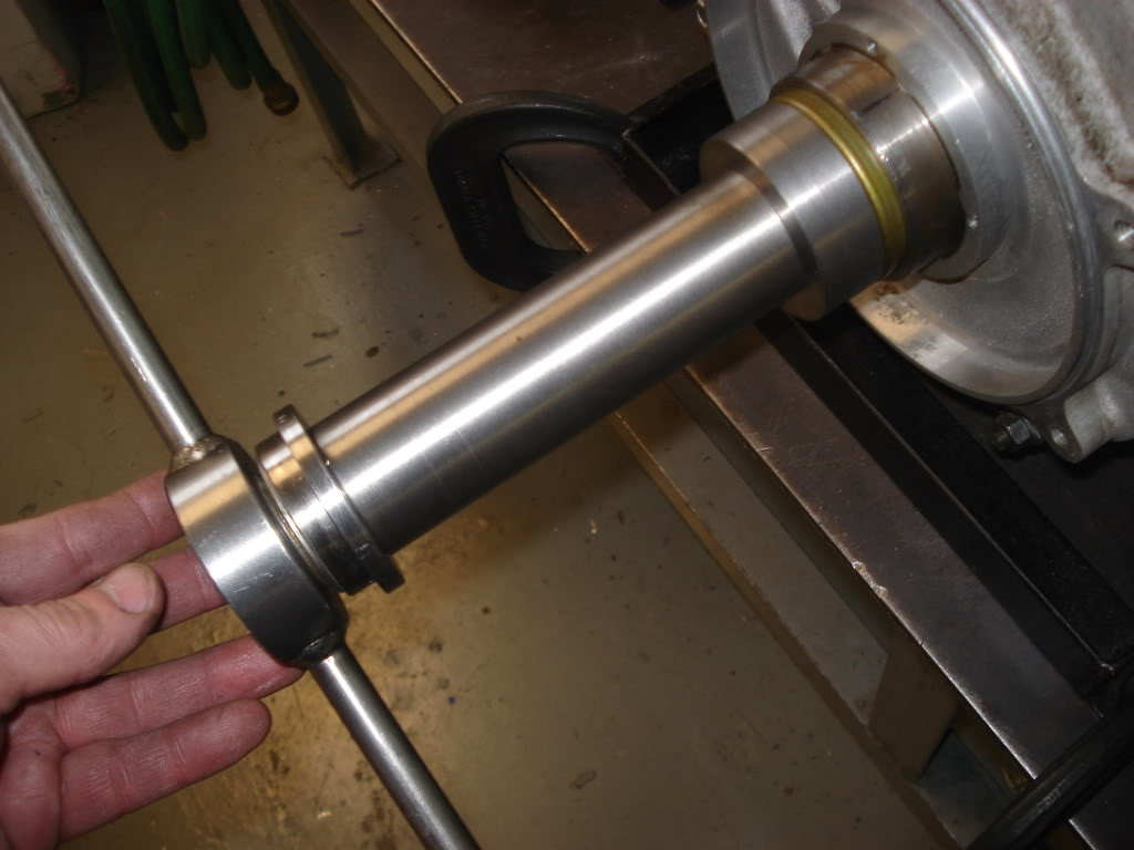
| Weld an extension shaft to a coupling nut, cut a piece of gas pipe the same diameter as the inner bearing race, welded a stud to the side of tube so it will stop the tube from spinning while tightening and eliminating the possibility of any metal shavings getting into the bearing while tightening the nut. Make sure the extension is long enough that you can grind a flat on each side of it so you can hold it with a wrench tightening the puller nut 17) |
||
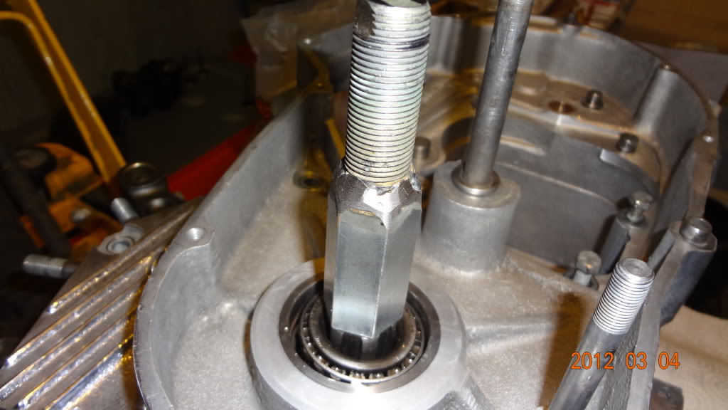 | 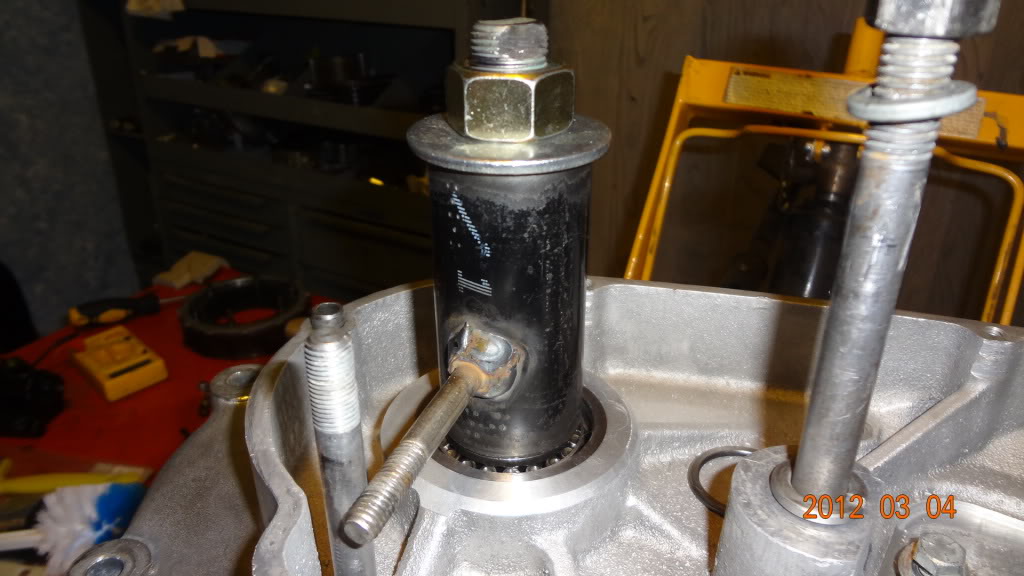 | 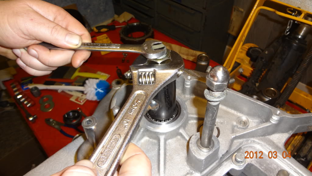 |
| Flywheel Installation Tool 18) | ||
|---|---|---|
 | |  |
 |  |  |
 |  |  |
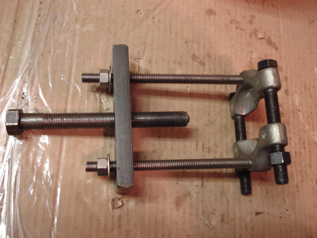
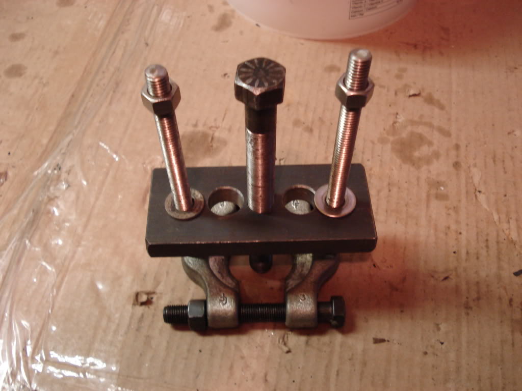
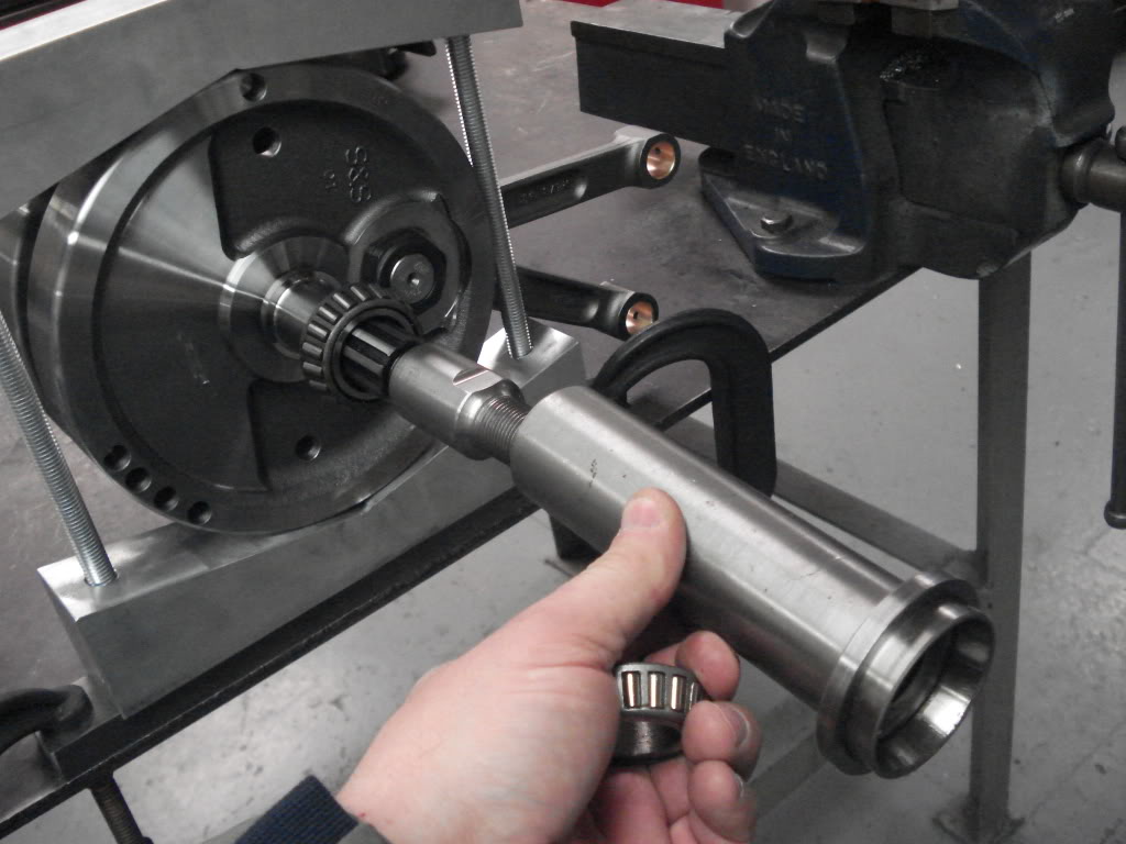
| Homemade tool to pull the flywheels back into the left case, pressing the bearing on and pull the wheel in at the same time.19) | ||
|---|---|---|