Table of Contents
This is an old revision of the document!

REF: Tools - 133
Pinion Gear, Pinion Shaft Runout Tools
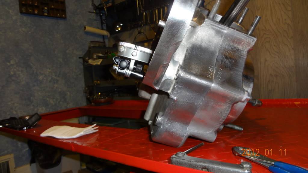
Pinion Gear
90 and Prior Models (4 Speed)
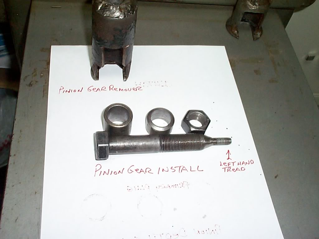 | 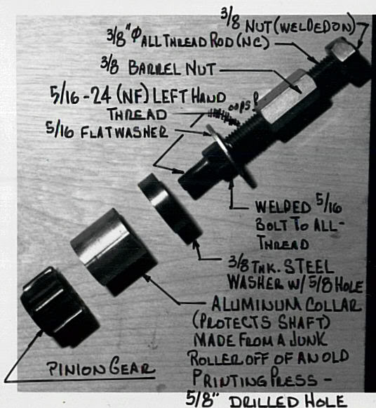 | 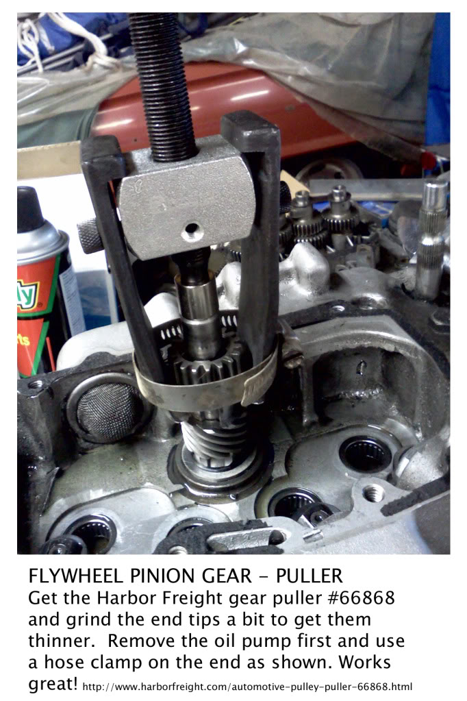 |
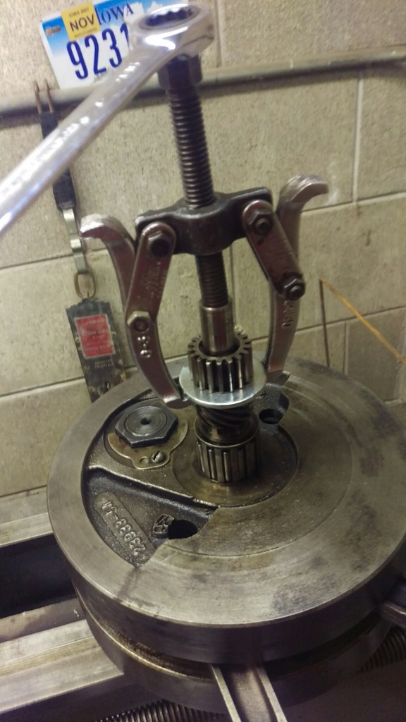
| Homemade Pinion Gear / Removal / Installation Tools 1) | Homemade pinion gear press 2) | Pinion Gear Puller 3) |
|---|
 | 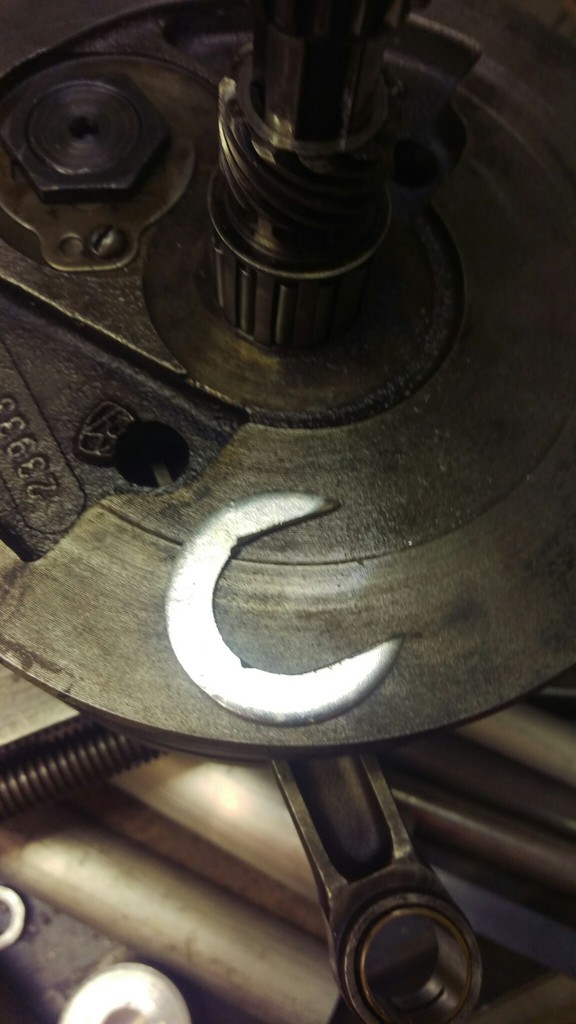 | 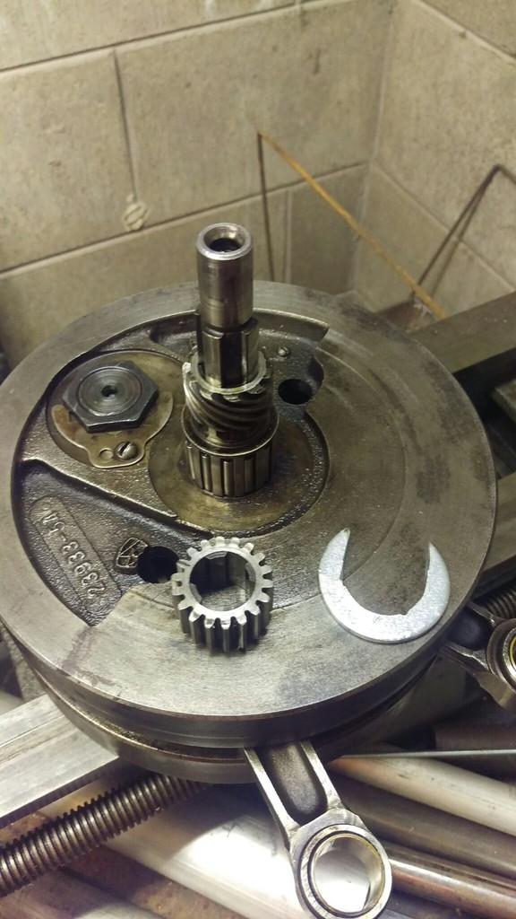 |
| Large fender washer cut into a “C” shape and a gear puller | ||
| Homemade Pinion Gear Puller 4) | ||
|---|---|---|
 |
| 3/8“ stainless steel plate with 20° spokes (for 18 teeth), sawed initial groove to depth and widened it with files |
| Homemade pinion gear locking tool for '89 models 5) |
|---|
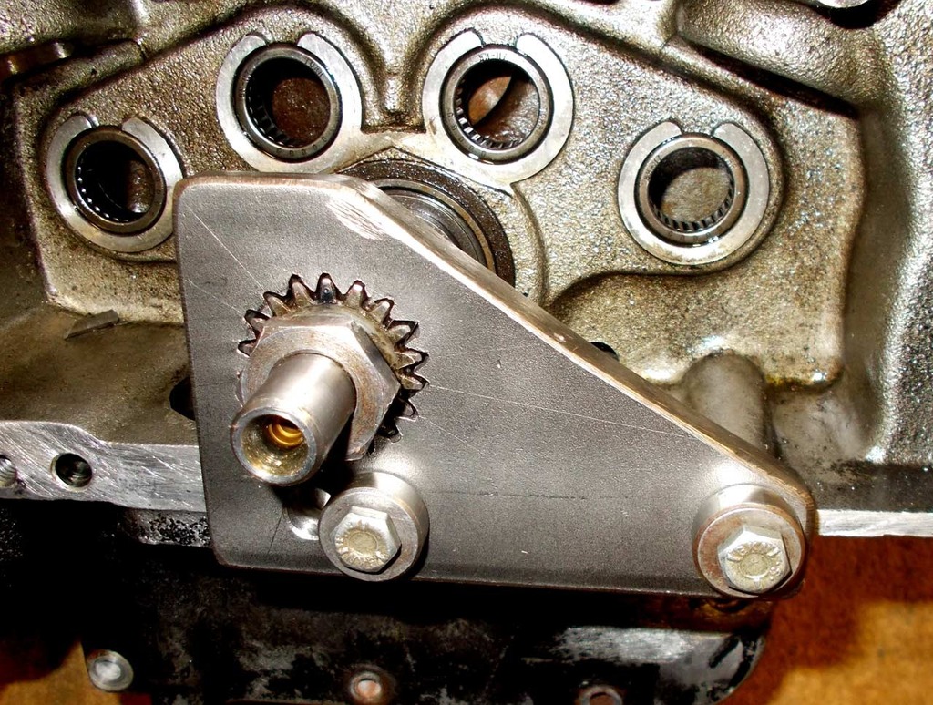
91 and Up Models (5 Speed)
See also Oil Pump Drive Gear in the Evo section of the Sportsterpedia.
For turning the engine over using the pinion gear nut
| You can use a 15/16” wrench or deep well socket to turn the engine over using the pinion gear nut. 6) | |
 |  |
| 93-Present Pinion Gear Nut (7916A) 7) | |
|---|---|
To remove or install the pinion gear nut
You'll need to lock the pinion gear from moving while turning the nut.
- It's very important to hold the crank on the pinion side with an appropriate pinion locking tool whenever you take the pinion nut off or put it on.If you hold the crank still from the primary side (or by putting the bike in gear and holding the brake), the twisting torque applied to the pinion nut gets transmitted through the crank, from one side to the other. The crank pin is not designed to resist much twisting force. You'll risk scissoring the crankshaft (knocking the crank out of true), which requires a full tear-down to fix. 8) So this is one of those situations where it's best to use the proper tool. 9)
Origin of the Grindlock Tool
From XLFORUM member, “ ~Grind~ ” 10)
(I) broke a tooth off the pinion gear upon applying 70 ft./lbs. of torque to the pinion gear nut per the Zipper’s cam installation instructions. 11)
 |  |
I torqued the pinion gear to 70 ft. lbs. using a tool I made just for this purpose (below).
I had another friend of mine scribe “HAMMER PERFORMANCE” on it and then sent it to Hammer Dan as a token of my appreciation for all of his help. 12)
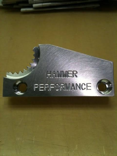 |  |
The folks at Hammer Performance worked out the bugs on a CNC lathe and named it the “Grindlock 2000” (homage to the creater, ~Grind~). 13)
It is machined out of 6061 T6 billet aluminum. The Grindlock 91-99 was soon to follow.
It holds the pinion gear and shaft securely while you loosen or tighten the pinion nut, without transmitting the torque through the flywheel assembly.
This is critical, because applying torque through the flywheel assembly can easily knock it out of true, necessitating a full tear down to fix.
 |  |  |
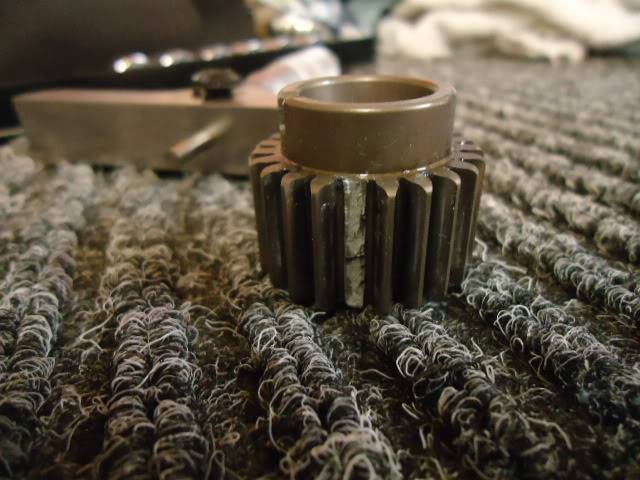
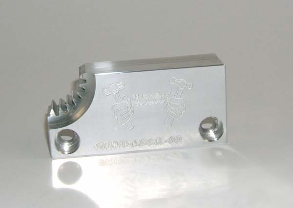
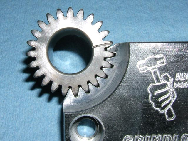
Note the tips of the teeth are cut down.
If the point on the nut happens to line up to the valley between two teeth on the gear,
You need to still be able to get the tool on. 14)
The tool slides over the gear, it doesn't slide in from the side.
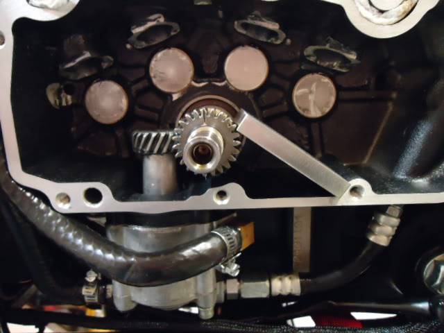
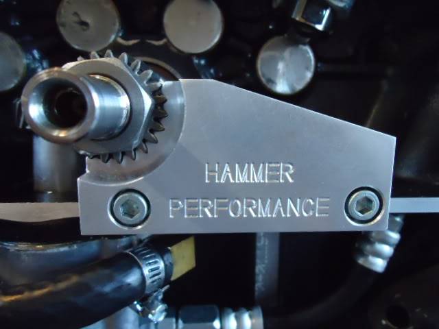
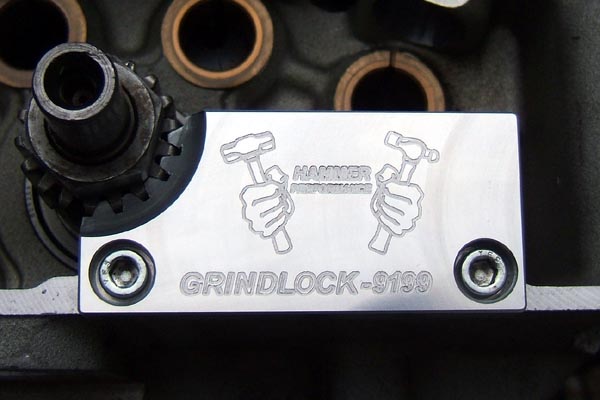
| The Grindlock Pinion Shaft Locking Tool engages for the full depth of the pinion gear for max. strength. 15) | Due to a change in the pinion gear in 2000, there are 2 different versions of this tool: 1. (91-99) year models & 2. (2000 to present) year models 16) |
|
 | 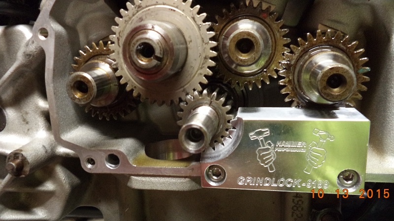 | 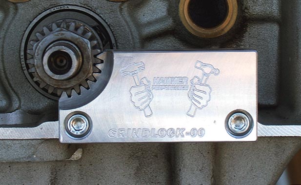 |
| Grindlock 91-99 & Grindlock 2000 (designed by XLFORUM member, “~Grind~” and Built by Hammer Performance 17). 18) |
||
|---|---|---|
How it's made:
Article by aswracing of the XLFORUM 19) … and Hammer Performance 20)
(click on a pic to enlarge)
The tool is CNC made with CAD/CAM software.
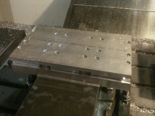
| Grindlock 2000 This is the first tool off the production line. | Grindlock 91-99 This one followed shortly after |
 |  |
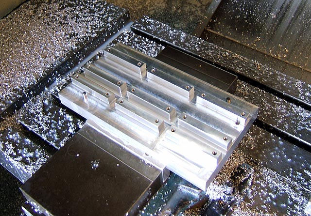
Step 1
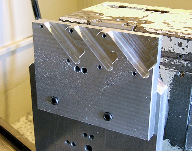
It starts with a slab of aluminum clamped in the step jaws of a vise.
The back side is cut with mainly flat end mills and some chamfering with ball mills.
Note that the upper left and lower right pieces have a hole in them.
This hole doesn't go all the way through.
It's used for alignment to the dowels in the fixture jig.
 |  |
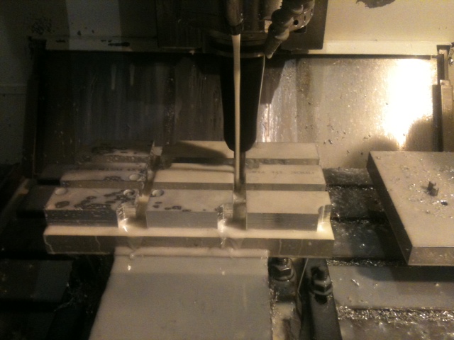
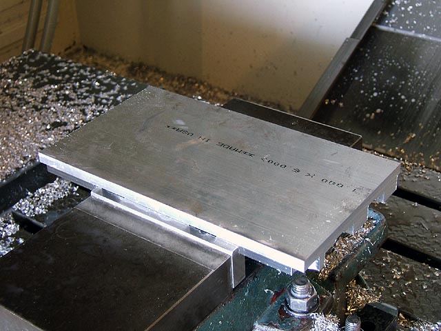
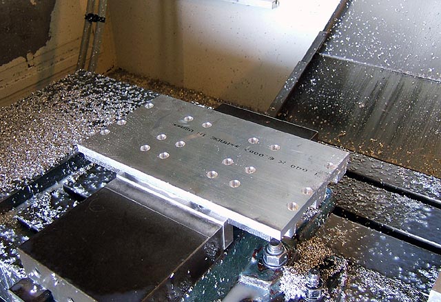
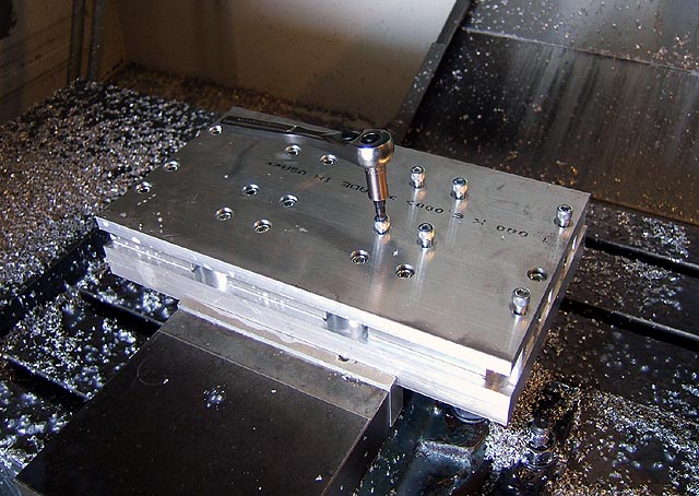
Step 2
The material is flipped over and clamped to the protruding portion of the pieces cut in step 1.
Holes are cut and counter-bored with small end mills (a 3/16“ for the hole and a 1/4” for the counter-bore).
 |  |
This jig was made to allow each tool to be cut from the material block.
Threads are tapped into the fixture and it will bolt to the material block with 18 screws (9 blocks with 2 bolts each).
It's got protrusions to support each block (there's a step in the back of each) and dowels in the corners.
It's very important to maintain proper registration and the dowels work very well.
 |  |
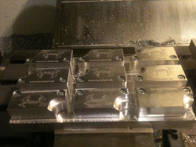
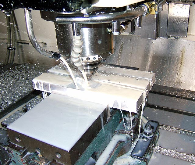
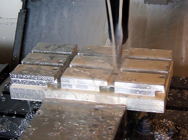
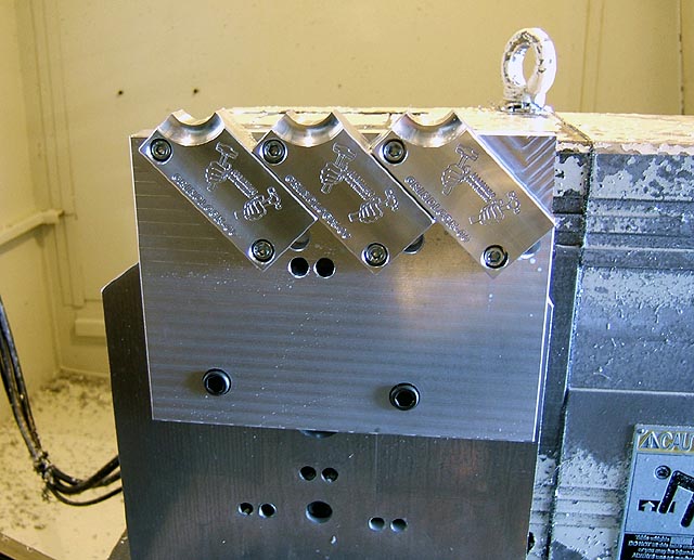
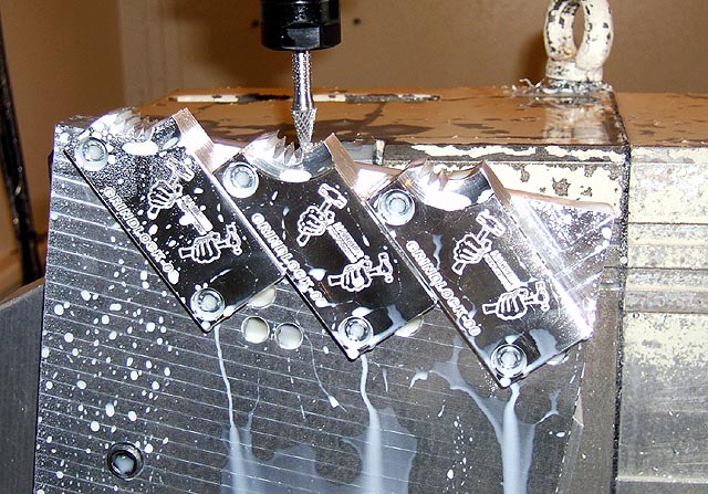
Step 3
Each tool is cut out of the material block, engraved and the pieces are faced off (clean straight ends).
 |  |
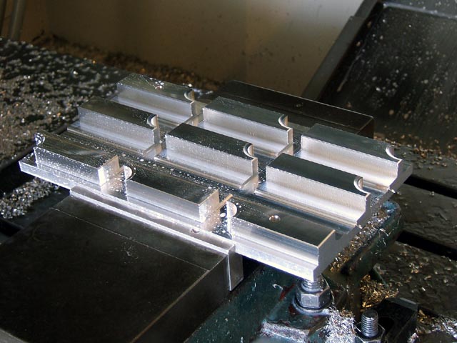
Step 4
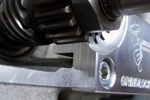
The teeth are cut next.
This requires another jig to hold the tools (3 at a time) for the tooth cuts.
It sits on the face of the rotary table.
Alignment and registration is provided by both a dowel and also by a notch on the back side that you can't see.
The slots are at a 45° angle and are very precisely cut to provide registration to the blocks.
The cutter used is a carbide burr,straight 20 degree included angle.
It has pretty fine serrations for cutting steel and doesn't seem to plug up while cutting (.010“ per pass).
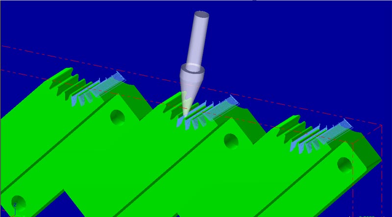
The CAD/CAM has a lot of advantages in terms of being able to;
A). Backplot & simulate to spot problems.
B). Easily adjust things and adapt and make changes.
Plus when doing rotary work it solves a whole lot of the math for you.
The picture below and to the right is a backplot of the tooth cuts.
Note how the tool is at an angle. It simulates the rotary.
 |  |  |
The table turns to one angle and cuts one tooth on each block.
Then the table turns to another angle and cuts one tooth on each block, etc.
The cutter's shape is not an exact match for the tooth.
But, two passes are made at each depth (each at a slightly different “Y” location … just a few thou apart).
This allows precise control of the tooth fit by varying this distance between the two parallel cuts.
That way, the tool fits just right over the pinion gear (not too tightly or too loosely).
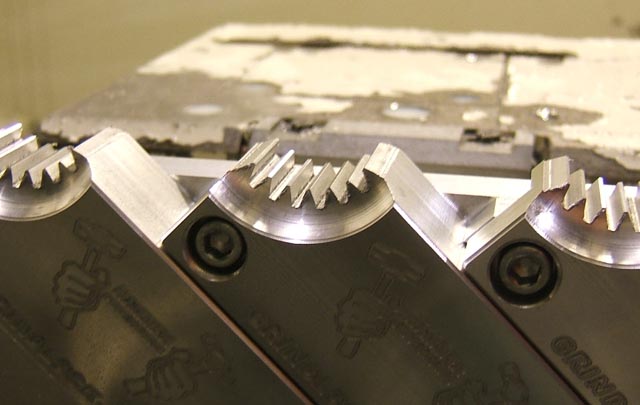
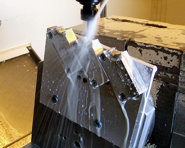 |  |
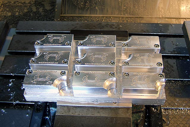
Here's what they look like when they're all done being cut.
The very last tool path goes in and knocks down the very tip of each tooth.
This is necessary because if you don't do it, the tip of the tooth hangs up on the pinion nut.
Next, to de-burr the teeth at each end with a small scotchbrite pad on an air operated die grinder.
 |  |
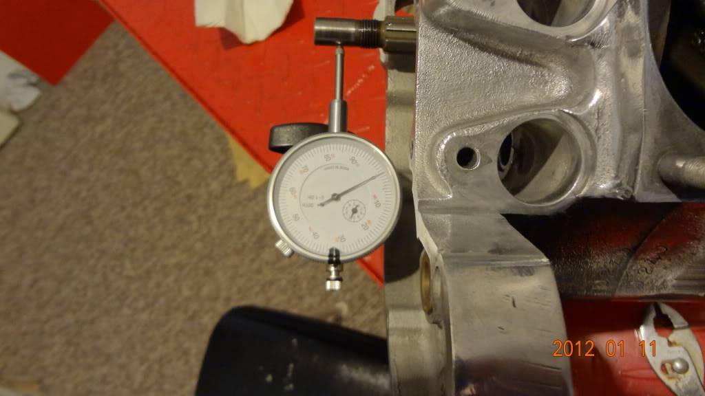
Pinion Gear Runout
| Attach a scrap piece of metal to the outside of the gearcase and position a gauge holder on it so it won't move while turning over the engine. 21) | ||
 | 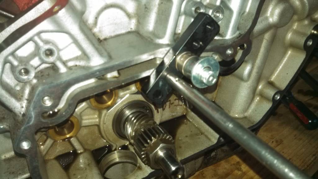 |  |
| Install a dial gauge on the holder with the pointer on the pinion shaft. Find the lowest spot while turning the engine over and 'zero' the indicator. 22) | This setup is made with a piece of angle iron for the magnetic base to stand on 23) | |
 | 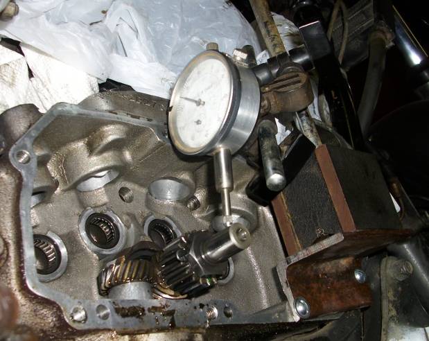 | 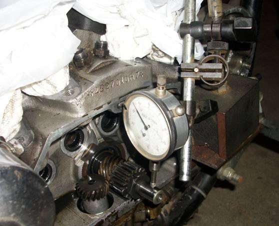 |
| This gauge post is threaded into a cover mount hole. 24) | |
 |  |