This is an old revision of the document!

EVO: Oiling & Lubrication
Engine Oil Routes
Right Crankcase Feed Galley
86-90 engines
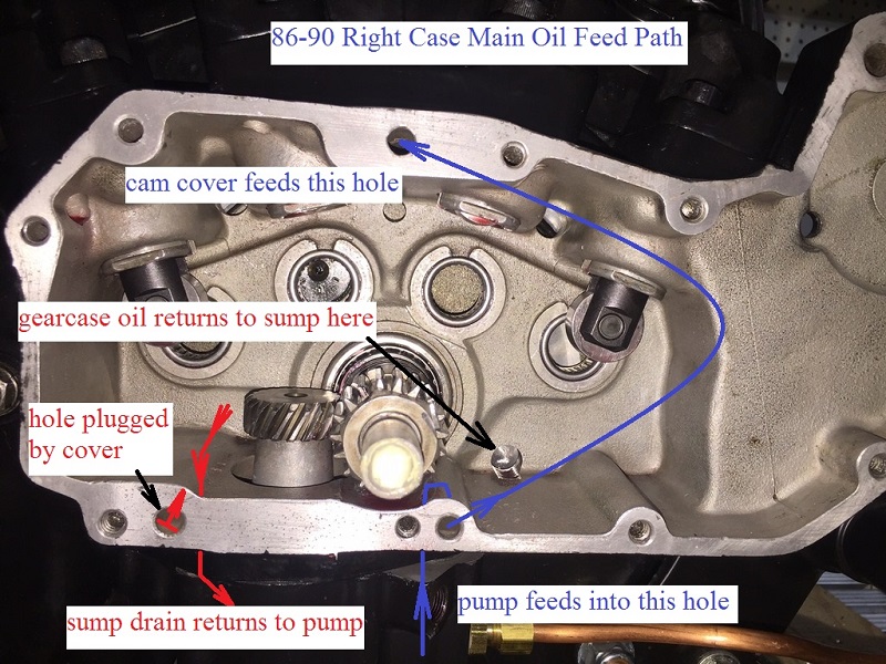
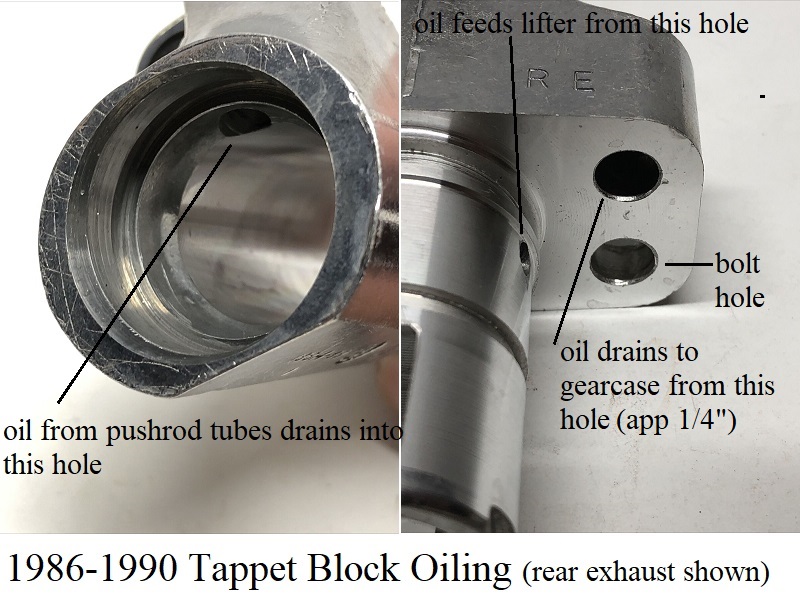
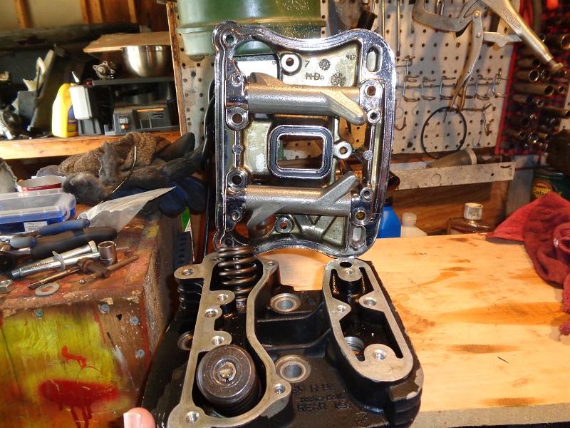
The lifter oil feed galley is a hole located along the top of the case between both intake tappets.
- The feed galley is responsible for carrying oil to the lifters.
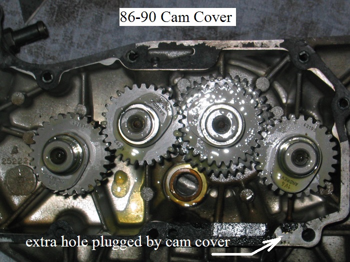
- It gets it's oil from the cam cover.
- A hole is internally routed from the top to the bottom of the cover with a hole exiting in a corresponding hole in the case.
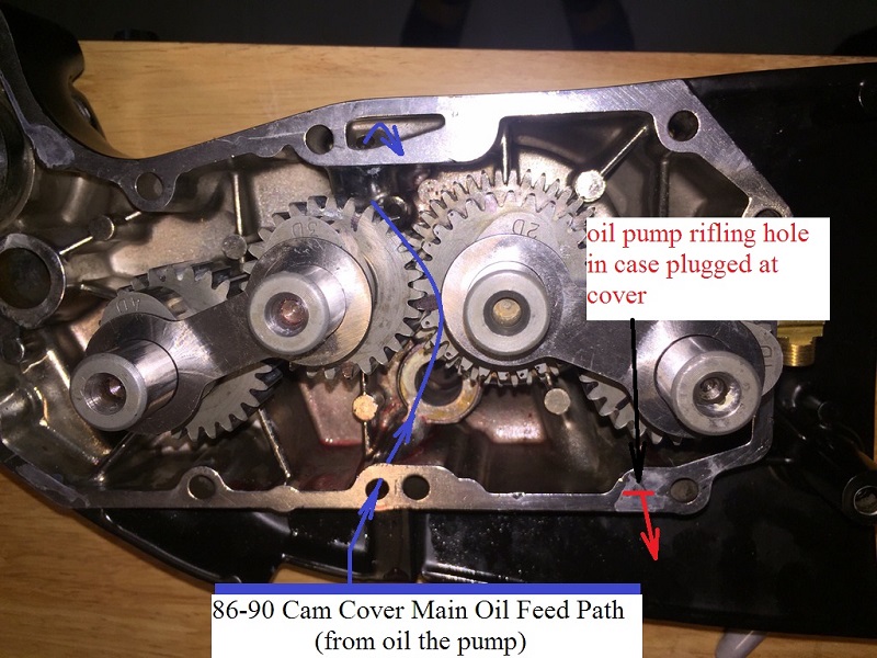
- The cam cover gets it's oil from the oil pump via intersecting holes between the bottom of the case and the cover.
- Feed oil is routed inside the cover but not to the gearcase.
- The hole in the middle of the case at the top intersects into the internal oil feed galley.
- Cross drilled passages intersect the main feed galley and carry oil to each intake lifter.
Exhaust lifters are fed oil (bore to bore) from a drilled passage into each one's respective intake lifter bore. - This is the end point of static oil pump pressure to the top end.
- The lifters supply oil pressure to the rocker boxes.
| 86-90 main oil feed path 1) | |
 |  |
91 and up engines
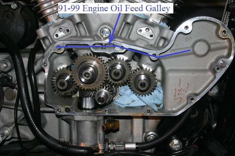
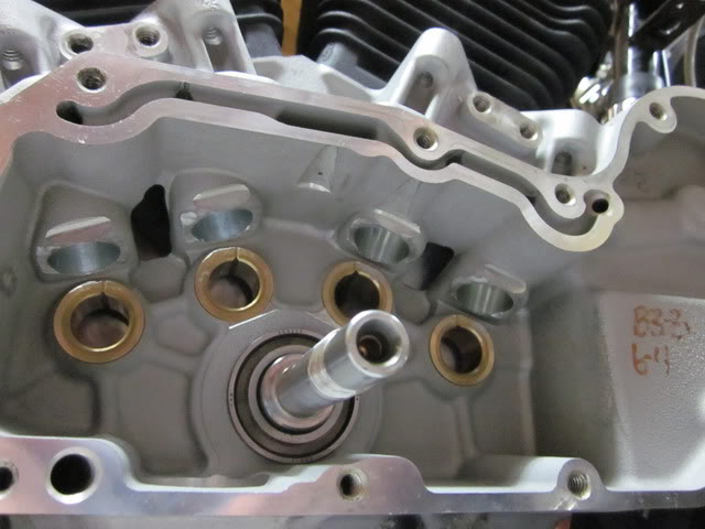
The main oil feed galley is a horizontal passage located along the top of the case beside the tappet blocks and lifters.
It runs from the filter pad to the last lifter bore (lifter for #1 cam).
This oil galley feeds the lifters, cam cover / pinion shaft / hole in pinion gear to the rod bearings and also the gears on cam #2.
- The feed galley is responsible for carrying oil into the engine.
- It gets it's oil from the filter / check ball.
- 91-99 engine feed galley is an internally drilled hole in the case.
- It runs behind and into on both sides of the small cavity (small slot) milled into the outside edge of the case.
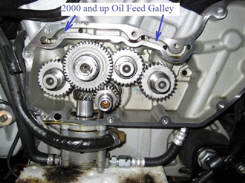
- 2000 and up engine feed galley is an external slot milled into the outside edge of the case.
- The oil passage runs on the outside (right) of the lifter bores as in 91-99 cases with a hole drilled through it into each lifter bore.
- Cross drilled passages intersect the main feed galley and carry oil to each lifter from the feed galley.
- This is the end point of static oil pump pressure to the top end.
- The lifters supply oil pressure to the rocker boxes.
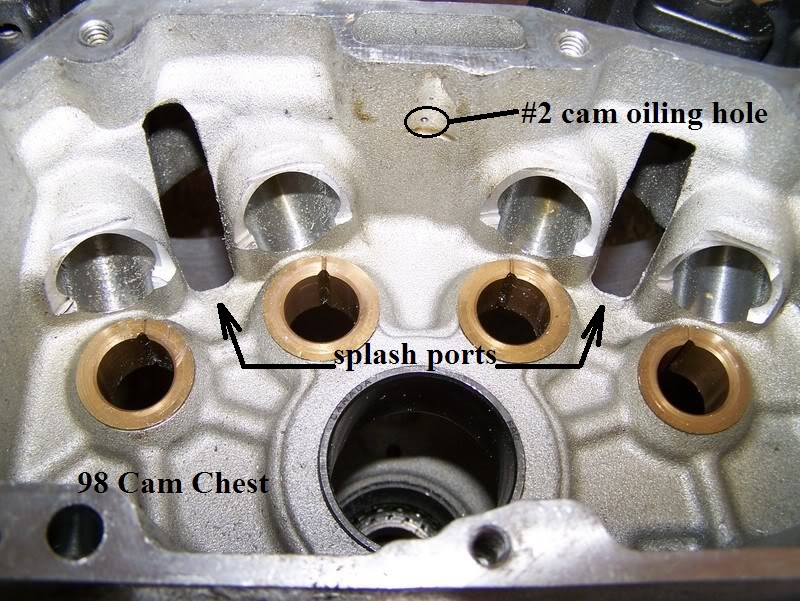
- A small amount of oil sprays down onto the rear intake (#2) cam gear through a tiny hole in the middle of the feed galley.
- The cam cover gets it's oil from an intersecting passage in the feed galley at the top of the cover.
(the gearcase gets no oil from this passage in the cover, outside of spill from the pinion shaft bushing)
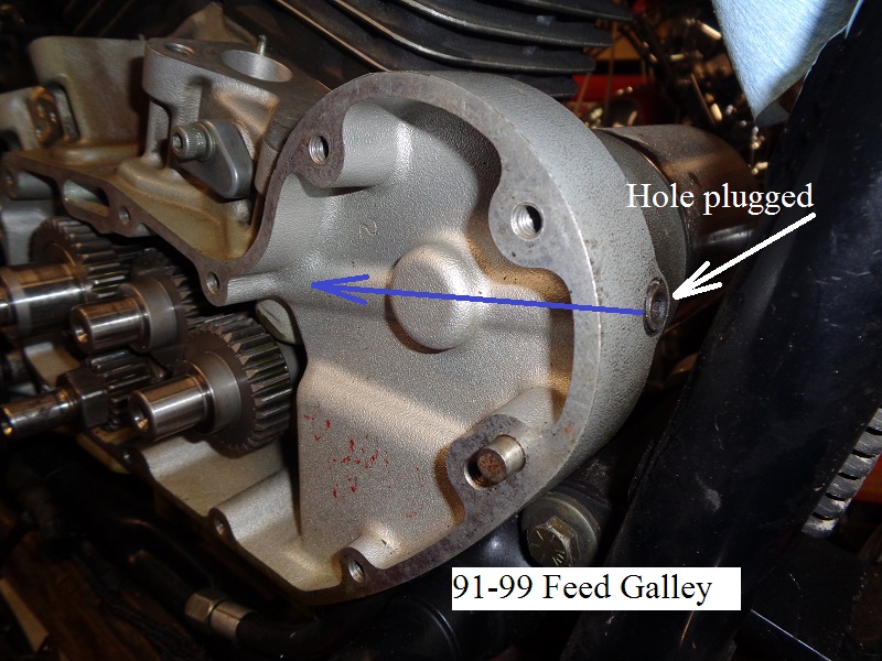
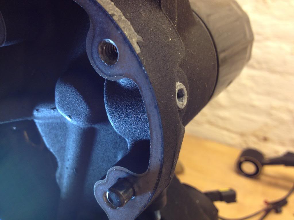
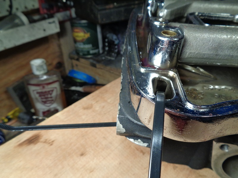
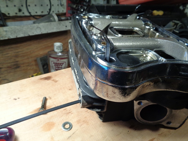
In examining the area directly behind the filter inside the gearcase;
You can see the oil path (channels from the filter to the engine).
There is a plug on the outside case in the area of the filter.
The plugged hole is from where the MoCo drilled the oil passage to connect the outlet of the oil filter to the lifters. 2)
After they drill it, they stick a plug in it.
There are other plugged holes like that on your motor where the drilling operation left a hole that had to be plugged.
Bottom End Oiling
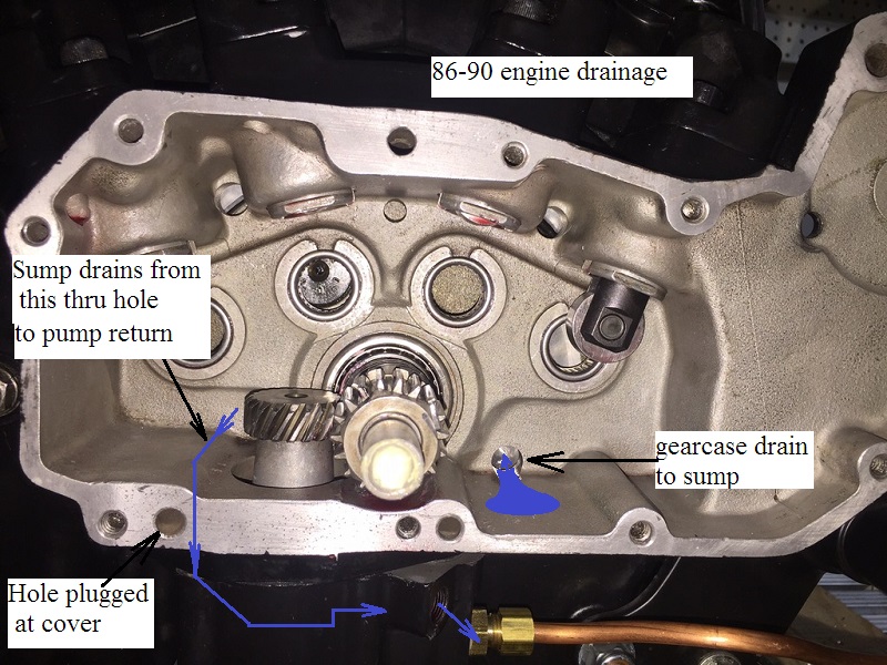
Case Oiling and Drainage
86-90 Engines
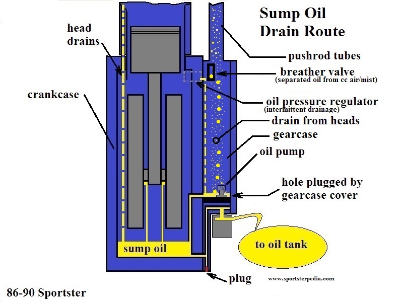
Gravity Drains
- Gravity oil (drained from rocker boxes and head/cylinder drainage) falls on moving parts and into the crankcase.
- Oil collected in the rocker box is returned to the crankcase through a passage in the cylinder and the head.
- Oil collected in the push rod areas of the heads / rockers flows down the pushrod covers.
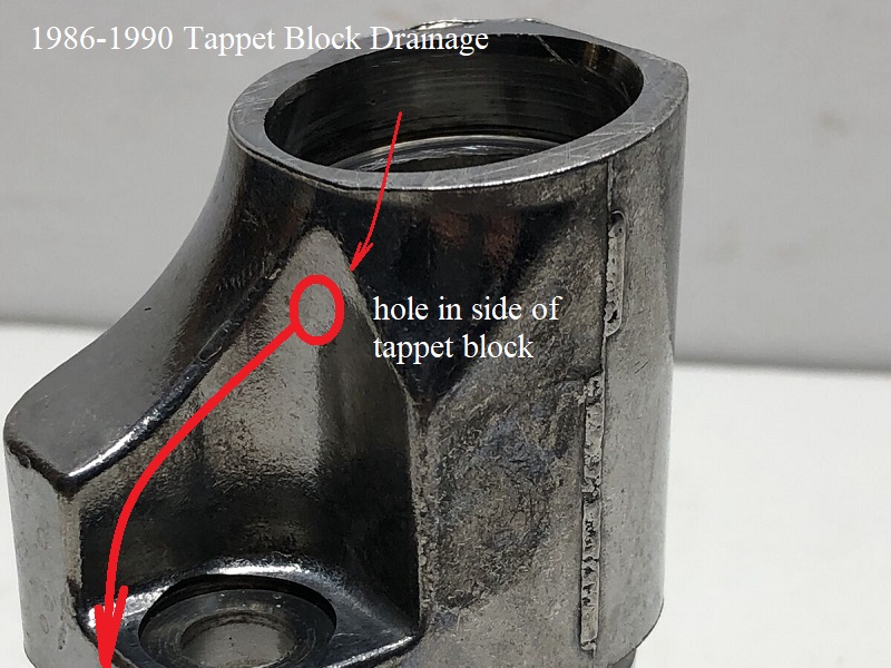
- Then it flows down into the gearcase / cam chest through drain holes through in the tappet blocks.
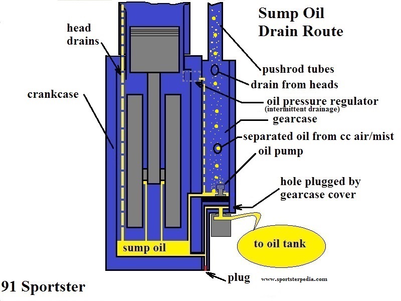
- Collected oil in the gearcase is routed to the crankshaft sump area via a low hole in the wall between them on the right side of the pinion shaft.
- Excess oil mist drawn into the gearcase breather is separated from crankcase air pressure at the gearcase breather valve.
- The separated oil (and condensed oil in the exit hose) flows into a drain hole below the breather valve and back into the gearcase.
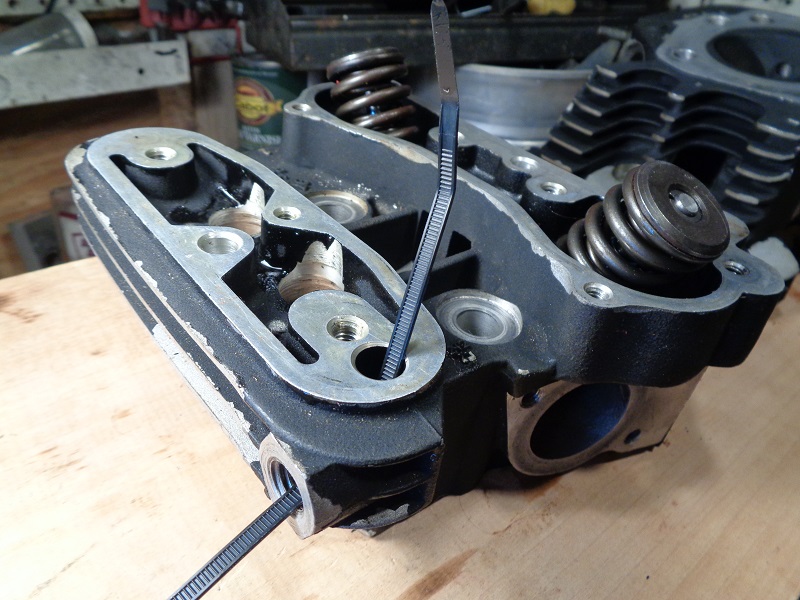
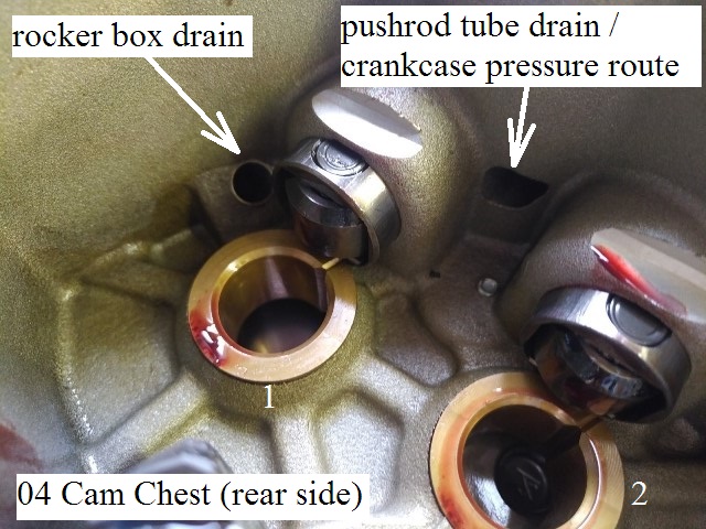
Tappet blocks are directional (rear exhaust shown below).
 8)
8)  9)
9)
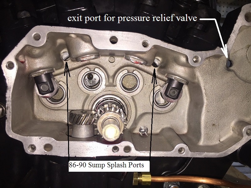
Splash
- Occasional excess pressured oil (from the oil filter pad) is dumped into the gearcase by the oil pressure relief valve.
- High pressure oil, when cold (on startup), opens the pressure regulator.
- The excess oil is dumped into the gearcase and routed to the sump area via the low hole in the wall between the gearcase and the crankcase.
- Splash oil in the sump area of the crankcase serves to lubricate the moving parts as well.
- Splash oil (from the up and down movement of the connecting rods, crankshaft and pressure generated under the pistons on downstroke) serves to lubricate;
- Cylinder walls
- Pistons, piston pins
- Cam gears and bushings
- Main bearings
| 86-90 engine sump splash holes 10) |
 |
Oil Pump Scavenge
91-Up Engines

Gravity
- Gravity oil (drained from rocker boxes and head/cylinder drainage) falls on moving parts and into the crankcase.
- (91 only) - Occasional excess pressured oil (from the oil filter pad) is dumped into the gearcase by the oil pressure relief valve.
- 91 engines kept the oil pressure relief valve that opens at 30-35 psi and dumps oil into the gearcase.
- The pressure relief was removed from future models.
- 91-03
- Oil collected in the rocker box is returned to the crankcase through a passage in each head and cylinder.
- Oil collected in the push rod areas of the heads / rockers flows down the pushrod covers.
- Then it flows down into the gearcase / cam chest through vertical drain holes in the tappet blocks.
- Excess oil mist splashed into the rocker boxes is separated from crankcase air pressure at the breather baffles (plain umbrella valves).
- The separated oil flows into drain holes in the rocker boxes and back into the crankcase.
| Rocker box drainage 18) |
 |
| 91-03 breather holes in the rocker box sections and head 19) | ||
 |  |  |
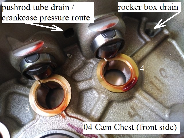
- 04-Up
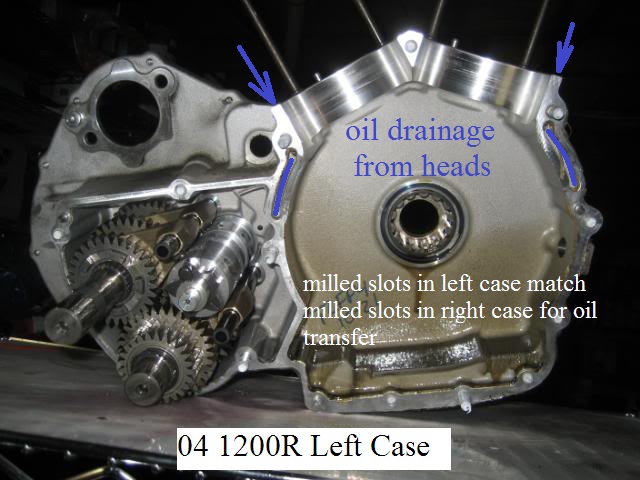
- Oil collected in the rocker box is returned to the gearcase through a passage in the head and the right case.
- Oil collected in the push rod areas of the heads / rockers flows down the pushrod covers.
- Then it flows down into the gearcase / cam chest through vertical drain holes in the tappet blocks.
- Excess oil mist splashed into the rocker boxes is separated from crankcase air pressure at the breather baffles (fancy umbrella valves).
- The separated oil flows into drain holes in the rocker boxes and back into the gearcase.
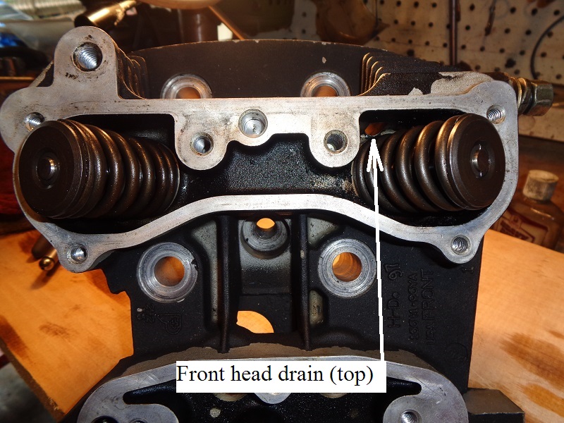
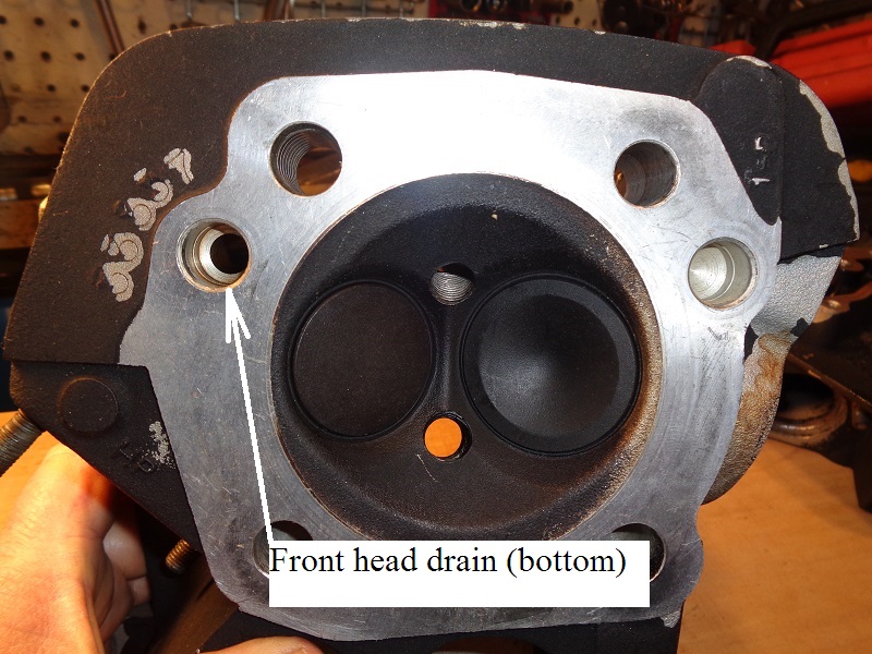
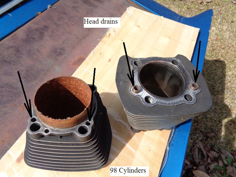
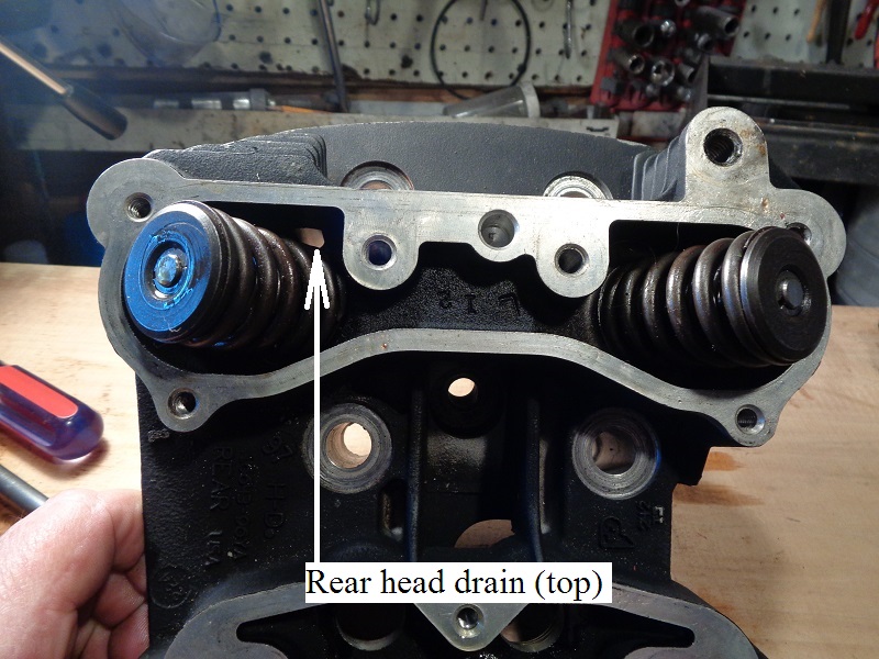
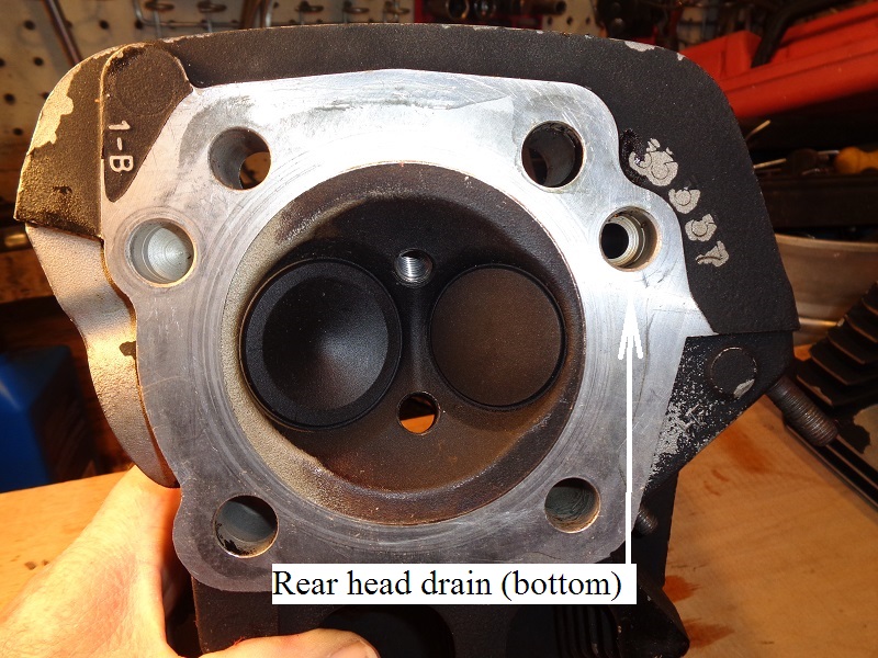
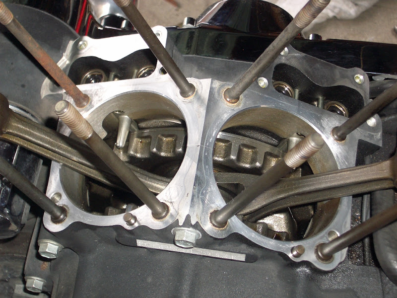
| Head drains in the cylinders 24) 1 hole is plugged on each cylinder during installation. | Head drains at the cylinder base on the case 25) |
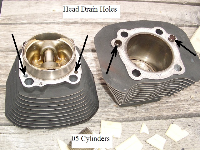 |  |
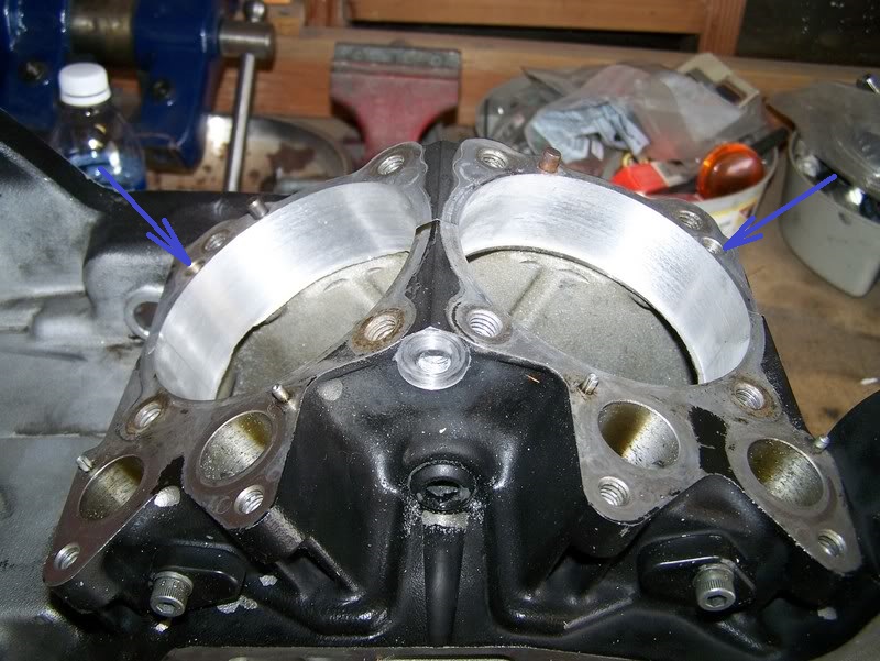
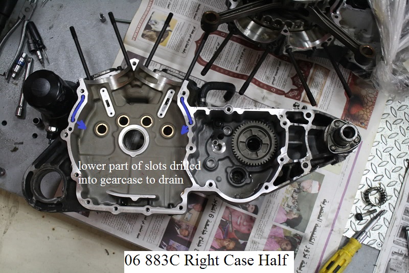
| Milled slots in the left case match milled slots in the right case for rocker box drain from valve side. 26) | Lower part of slots in the right case exit thru drilled holes into the gearcase. 27) | |
 |  | 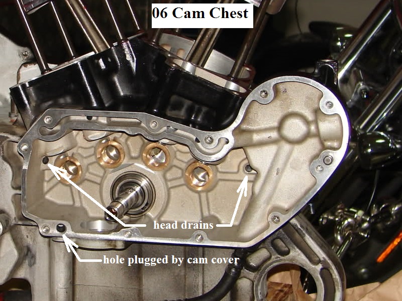 |
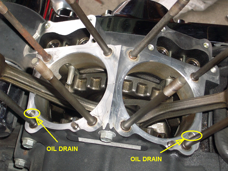
| Rocker box drains into the cam chest. 28) | |
 |  |
Splash
- Splash oil
(from the up and down movement of the connecting rods, crankshaft and pressure generated under the pistons on downstroke) - Crankcase pressure mixed with oil in the sump area serves to splash (and lubricate) the moving parts such as;
- Cylinder walls
- Pistons, piston pins
- Cam gears and bushings
- Main bearings
- Crankcase pressure also serves to help 'push' oil from the sump into the scavenger port of the oil pump.
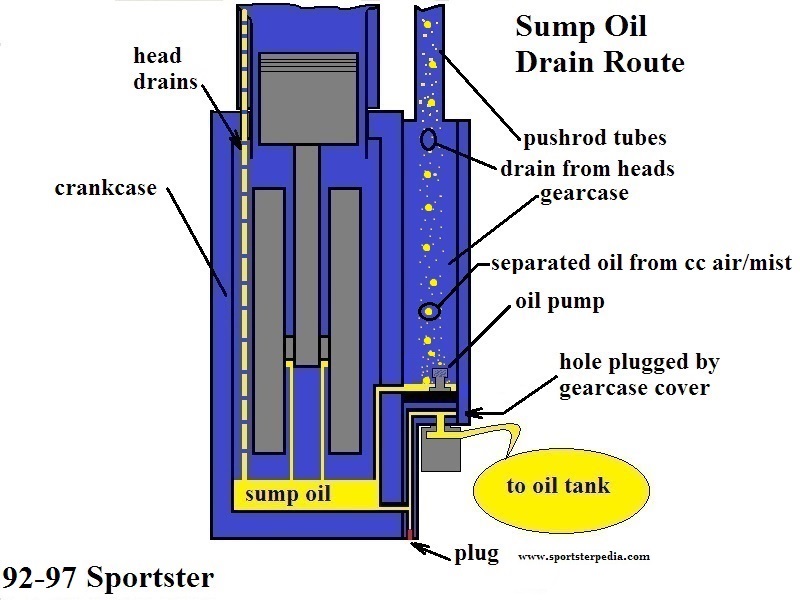
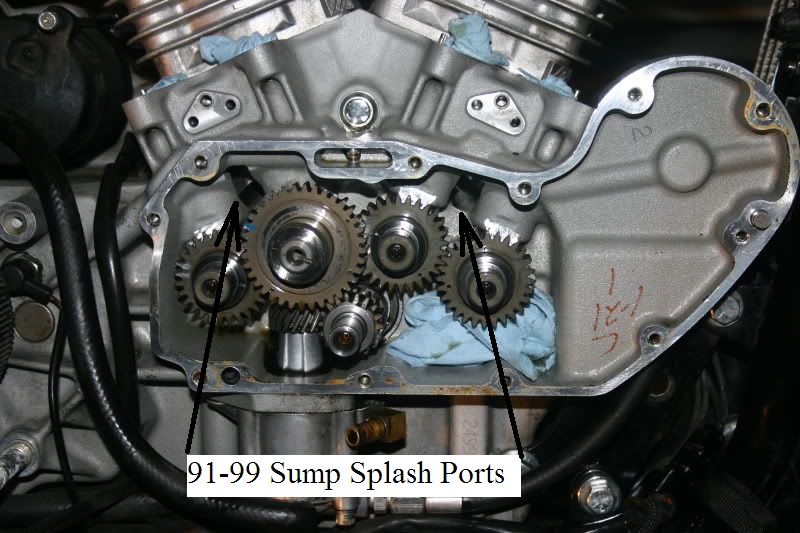
91-99
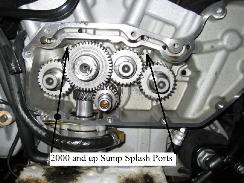
00-03
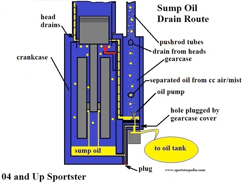
04-Up
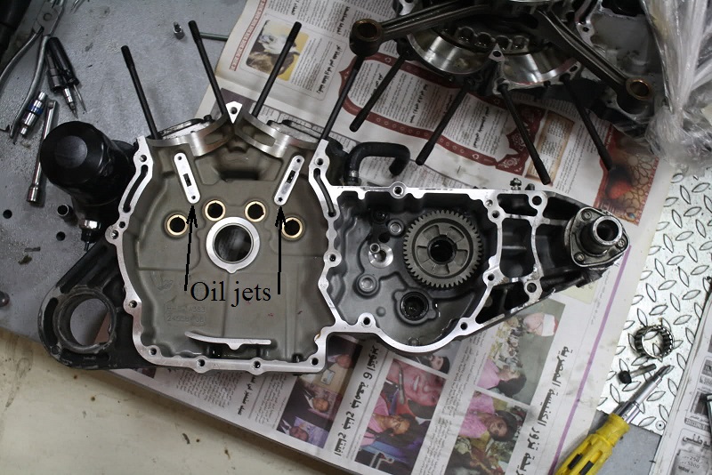
- The rubbermounts received an addition of piston oiler jets in the previous splash port locations.
- The holes in the cam chest wall from the inside no longer go through to the cam chest.
- Instead, the holes from the inside are passaged to the back of the lifter blocks where a drilled passage intersects into the oil feed galley. *
- Oil jets were installed there to direct feed oil up to the bottom of the pistons.
- The jets create a dual oil spray in a controlled direction upward to the pistons while crankcase pressure and out the ports in the wall for pressure venting.
- Pressurized air / oil mist leaves the crankcase through the bearing on the pinion shaft into the cam chest.
- There is no seal on the bearing and air pulses into the cam chest to be pulled up into vertical passages between the cam slots.

Oil Pump Scavenge
See also the Evo Oil Pump section of the Sportsterpedia.
- Drainage
- Oil collected in the crankcase sump is passage-routed to the scavenger side of the oil pump.
(by pressure generated by the downward stroke of the pistons and the scavenging effect of the pump)
Sump oil is collected by the pump at the 'ladle, half spoon, duck bill' protruding from the back of it where oil drops onto the scavenge gerotors.. 35) - Oil collected in the gearcase / cam chest is routed to a drain port in the top of the oil pump where it drops down onto the scavenge gerotors.
- Return oil fills a cavity above the pump's return gears from these dual inlets and pumps the oil back into the oil tank.
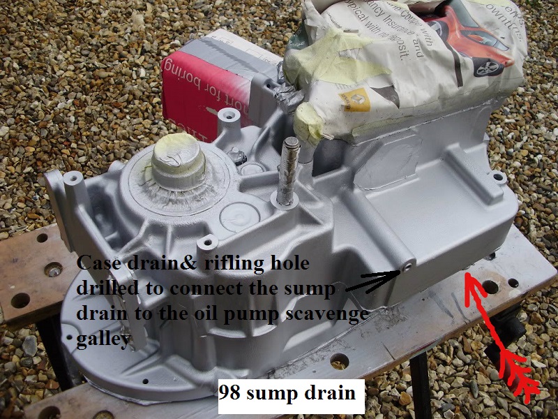
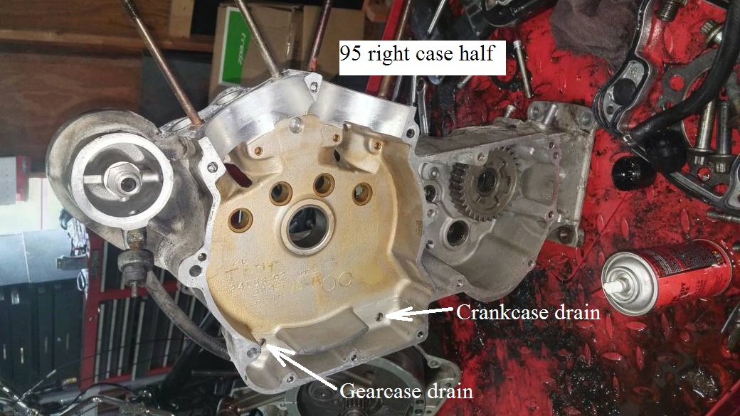
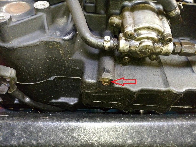
- Below is the case drain for a 98 engine. 36)
- It's also a rifling hole drilled to connect the sump drain to the oil pump scavenge galley.
- It could be plugged with a treaded pipe plug or a freeze plug.
| Case drain / rifling hole for sump drain 37) | Rifling hole is on the back side of hole on the right. 38) |
 |  |
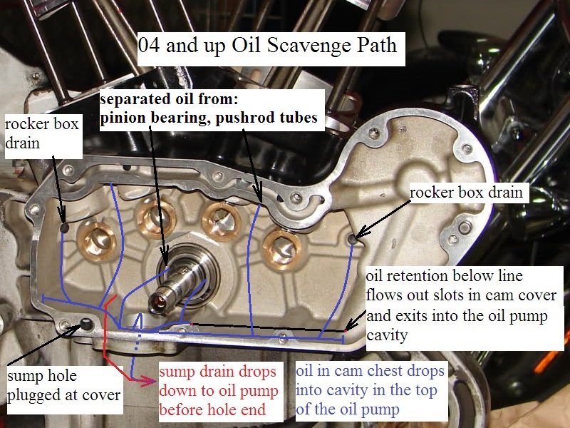
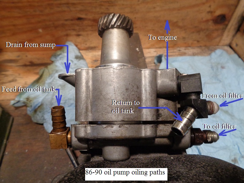
| 98 and Up Oil Pump Oiling Paths 41) |
 |