Table of Contents
This is an old revision of the document!

IH: Electrical System
 See the IH section for illustrated OEM wiring schematic drawings.
See the REF section for some simplified wiring diagrams/schematics.
Wiring
For electrical devices to function, they must have a completed circuit, from supply to device and back to the supply. The ironheads use a negative ground reference and distribute the positive voltage thru the wiring harness. The following is a generalized description of power and ground distribution that may not apply exactly the same to every model, especially the earliest models.
Grounds
Ironheads did not use any wires in the wiring harness for distributing grounds to devices. Even the EVO models up thru 1990 did not have ground wires in the harness. Instead, these models used the frame itself for grounding the various devices to complete their electrical circuit. For grounding the devices on the forks, the triple tree was grounded to the frame thru the neck bearings. For the isolated handlebars, there was a ground wire attached to one of the riser mounting bolts with the other end of the wire attached to the upper or lower triple tree bracket. Later models had additional wiring in order to more directly complete the electrical circuits back to the source - the battery or the regulator.
All (or most) of the devices on such models were grounded thru their mounting brackets or nearby onto the frame. Whether the power source was the battery, the regulator or the generator, it was grounded nearby on the frame directly or at the rear engine mount.
Power
The positive power source (battery/regulator) sends voltage thru a main circuit breaker or fuse wire to the keyswitch. Two circuits are supplied power by the keyswitch - the Ignition circuit and the Lights circuit - each with multiple devices. The devices on these two circuits are supplied with power thru the wiring harness.
Some devices (like turn signal lights) get power only after it runs thru activated switches or other devices. In these cases, the devices were always grounded but activated by positive power. Other devices (like the coil & indicator lights) get power whenever the keyswitch sends power on that circuit and they are activated only when a switch or device provides a ground to it. Later, the coil was only supplied with power when the RUN/STOP switch was in RUN mode.
The turn signals operated from one flasher, since the positive voltage output of the flasher was routed thru each handlebar TS switch before going to the appropriate lights (front, rear & indicator). These lights were grounded to the frame by their housing brackets.
Because there were no ground wires in the harness, it is VERY IMPORTANT that all mounting brackets for electrical devices make a good connection to the frame so that the device can be grounded and the electrical circuit can be completed back to the battery negative terminal.
On the wiring diagram for such models, there is only one wire shown going to the devices. This is the positive power wire. Sometimes the diagram showed the housing as grounded, but sometimes it did not show the device as grounded even though it was being grounded thru the housing. Where multi-functions occured within the same housing, such as the taillight/brake light, there are two wires shown running to that device, but both wires are bringing positive power, for each individual function, with the ground for both functions going thru the device mounting bracket.
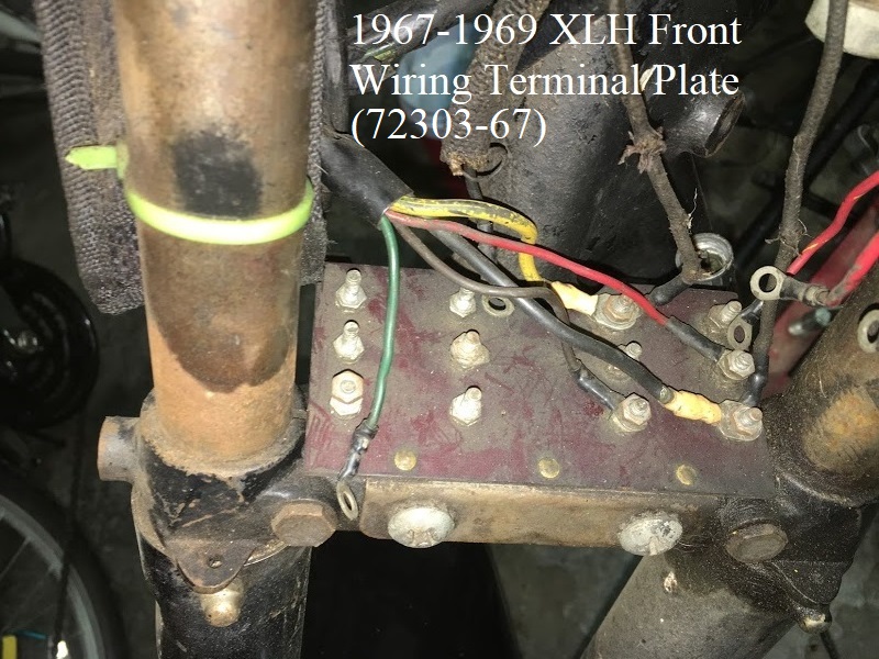
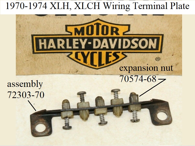
Wiring Terminals

Circuit Breakers
The circuit breakers have copper and silver colored terminals. The copper terminal is the input side for the battery. 4) The keyswitch is attached to the output side, silver terminal. Also, the wire from the regulator attaches on the (silver) output terminal, then passes current thru the circuit breaker in reverse direction to charge the battery. You should NOT run the output wire from the regulator on the copper terminal of the circuit breaker, nor directly to the battery positive terminal, because this would allow a failing regulator to short the battery to ground, pulling hundreds of amps of current from the battery and potentially causing a fire.
Diode
A diode is a one way electronic check valve that only allows current to flow in one direction. 5) On Sportsters, a diode is installed in the “Gen” light circuit to help determine if the generator/regulator is working correctly. If all is working the way it should be, with the bike running and everything working correctly, the generator/regulator will be producing a higher voltage than the battery (i.e. it's charging the battery). The voltages at each end of the diode will be such that the diode allows no electricity to flow through the circuit, and the “Gen” light stays off.
If your generator/regulator takes a big dump and stops producing the correct voltage, the battery voltage will be higher than the voltage being produced by the generator/regulator. The relationship of the voltages at each end of the diode will then be “reversed” from normal, and that will cause the diode to allow current flow. The “Gen” light will light up, telling you that something is wrong. That's why the “Gen” light lights up when you first turn the key on, as the battery voltage is higher than the voltage being produced by the generator/regulator, since it isn't producing any voltage with the engine not running.
Other Related Topics
In the EVO section: Battery Cables - The Place to Start
——- Also There: Battery Charge Level - Battery Voltage Readings - Testing For Proper Grounds