Table of Contents
This is an old revision of the document!

IH: Oiling & Lubrication
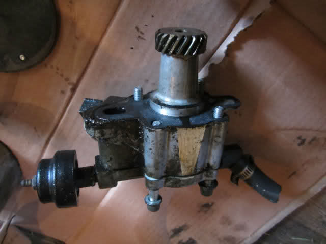
Ironhead Oil Pumps
XR-750 Oil Pumps (only)
- From 1972 to 1989, the gear driven oil pump went through several changes.
- The main body and design stayed the same. (as in the ball check valve assembly and seals) 1)
- 1972 - Feed pump speed was 1/4 of the engine speed and the return side operated at a 2:1 ratio of the feed side.
- The breathing system was used to return oil from the crankcase into the cam / gear cover.
- From there the oil drained directly onto the return gears of the oil pump. 2)
- 1975-1980 - The engine had a separate oil sump bolted to the crankcase.
- Return gears scavenged the crankcase oil through an external oil line. 3)
- 1989-2003 - The same design of the '75-'80 pump.
- But with a more efficient drive gear design and improved oil routing.
- The oil pump speeds were doubled to 1/2 of engine speed for the feed pump and a 4:1 ratio on the return side.
- The oil pump drive gear was re-activated as a breather only. 4)
Oil Pump Pressure (57-85)
Expected oil pump pressure per FSM's:
Gauge mounted at oil pump:
As checked with hot oil and a gauge at the oil pressure switch location at the oil pump.
The oil pressure switch has to be removed for the gauge to be installed.
1957-1969: 5)
Minimum: 3-7 psi (idle, with spark retarded)
Normal riding conditions: 10-14 psi (6 psi at 20 mph)
1970-1978: 6)
Minimum: 3-7 psi (idle)
Maximum: 15 psi (60 mph in high gear)
Normal riding conditions: 4-15 psi
1979-1985: 7)
Minimum: 4-7 psi (idle)
Maximum: 10-20 psi (3500 rpm)
Normal riding conditions: 4-15 psi
1957-1976
Sub Documents
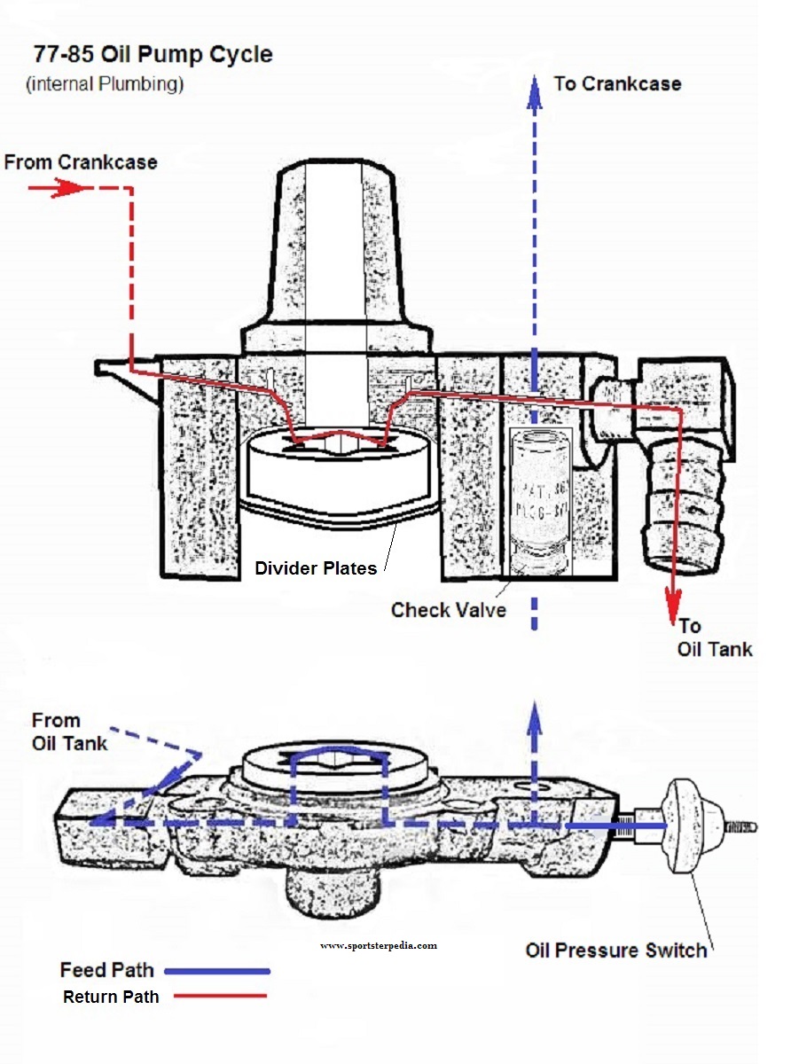
Oil Pump Cycle
- The separate oil feed and scavenger (oil return) pumps are gear-type pumps and are incorporated in the same pump housing with a check valve on the oil feed side. The feed section is gravity fed from the oil tank and forced fed from the pump to the engine and back to the scavenger side of the pump which returns oil back to the oil tank. 8)
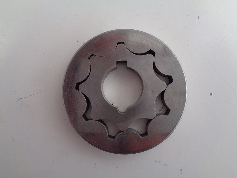
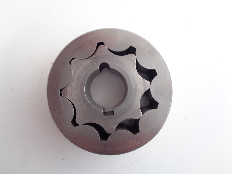
- In a gear type oil pump, the oil is transferred from the inlet to the outlet side of the pump when it is trapped between the rotating gear teeth and the gear housing.
- The oil pump seldom needs servicing. Therefore, before dis-assembling it for repairs because of no oil pressure, be absolutely certain that all possible related malfunctions have been eliminated. 9)
- If oil in oil tank is diluted, pressure will be affected.
- In freezing weather, the oil feed line may clog up with ice or sludge, preventing circulation.
- Inspect oil pump check valve as it prevents the gravity flow of oil into the crankcase when the engine is not running and provides the correct oil pressure for the operation of the oil signal light switch. If the check valve is not seating properly, oil will bypass the valve and drain oil from the oil tank into the crankcase and upon starting the engine, a considerable amount of oil will be blown out the crankcase breather pipe.
- Check for a grounded oil pressure switch wire or a faulty switch if oil indicator light fails to go out with the engine running.
- If no oil pressure or return oil is not indicated at the oil tank, when engine is running, or an excess amount of oil is blown from the breather pipe, dis-assemble the oil pump for repair. Damage can occur by way of a foreign object lodged in the oil pump gearing. Check your FSM for dis-assembly and repair. 10)
Production Oil Pumps
- There are 3 basic pumps 11)
- 57-E62 (3 variations) these use 16t body gears.
- L62-71 (2 variations) these use 14t
- 72-76 (no variations) use 16t again
- & 2 basic plumbing styles: 12)
- Both feed and return are drilled passages in the right crankcase (57-66 all) & (67-69 xlch)
- Only return drilled thru case. feed goes from tank to pump by external hose. (67-69 xlh) & (70-76 all)
- With the correct knowledge any 57-76 pump, or parts of them can be mated to any 57-76 cases. But the combos can get confusing. 13)
- The stock slot in pre & post -72 pump bodies are .345“ 14)
- The stock slot in pre -72 pump gear is .375” 15)
- The stock slot in post -72 pump gear is .625“ 16)
| 1967 XLCH Oil Pump 17) | |
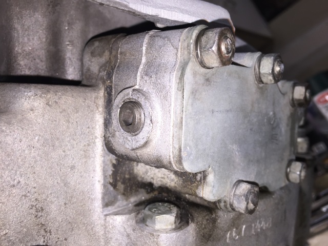 | 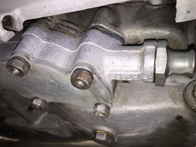 |
1977-1985
Sub Documents
Oil Pump Cycle
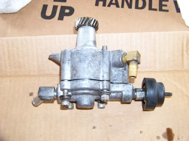
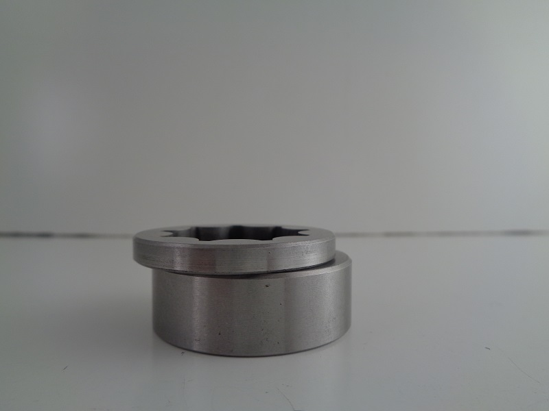
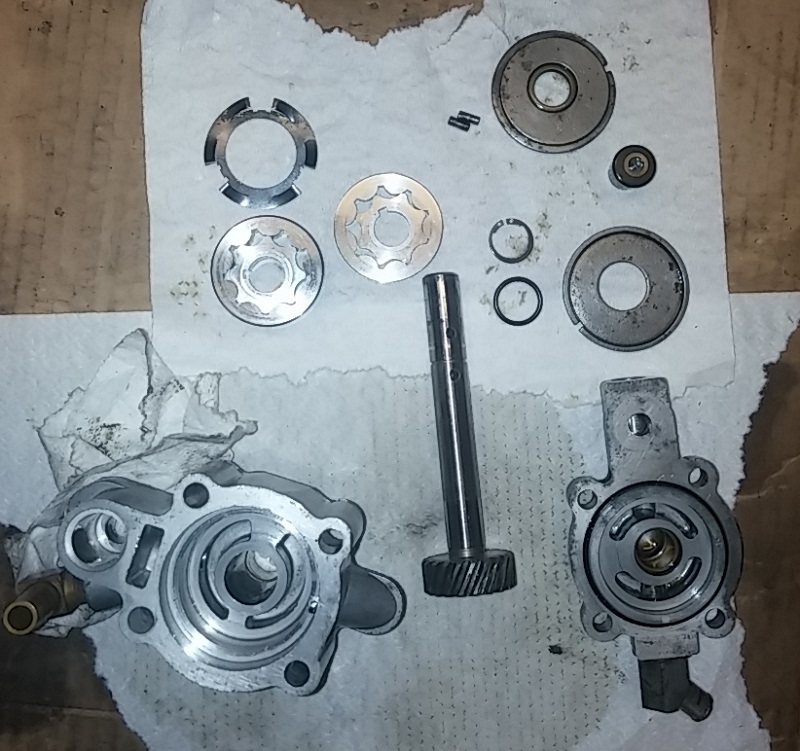
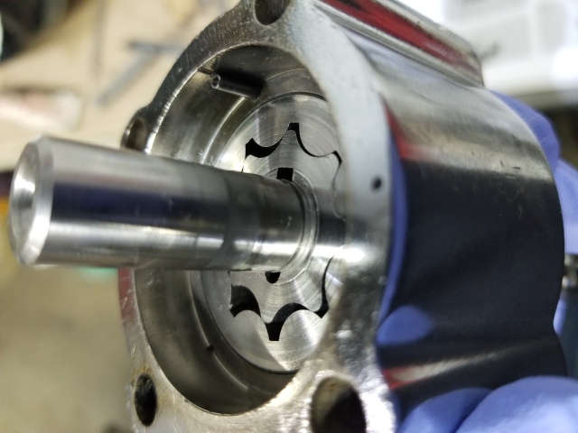
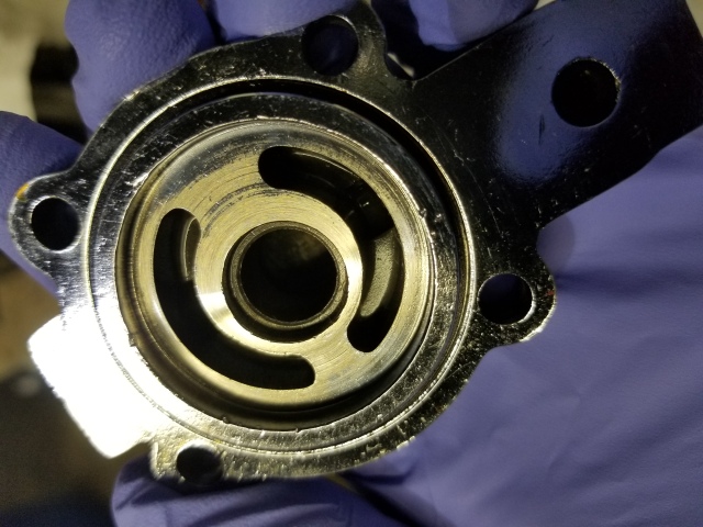
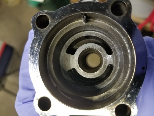
- The oil pump is fitted with gerotors instead of gears consisting of two gerotor pumps in the same pump housing.
The pump is gravity fed from the oil tank. The feed pump forces oil to the engine while the scavenger pump collects and returns oil back to the oil tank. - A gerotor type pump has 2 elements, an inner (which always has one less tooth than the outer) and an outer gerotor.
Both elements are mounted on fixed centers but are eccentric to each other. 18)
- In a gerotor type pump, oil is transferred from the inlet to the outlet as it is trapped between the rotating inner and outer gerotors. 19)
- All Sportster gerotor pumps (77 and up) turn clockwise when viewed from the top.
(as opposed to 76 and older pumps that turn counter clockwise) 20)
- The gearshaft is in a worm gear configuration with the drive gear on the pinion shaft.
- During the first 180 degrees of rotation, the cavity between the inner and outer elements gradually increases in size.
Maximum cavity volume is equal to the full volume of the missing tooth.
The gradually enlarging cavity creates a vacuum into which the oil flows out from the inlet. - During the next 180 degrees of rotation, the size of the cavity decreases forcing oil into the outlet.21)
- Oil is forced into a valve with a one way spring loaded cup set at 1-1/2 psi.
From that valve, oil exits the pump and enters the crankcase. Oil pressure is indicated by the oil pressure switch. 22)
- This pump has two hose fittings; 24)
- The rear fitting is the oil feed.
- The front fitting (above the oil pressure switch) is the oil return.
- Simplified cycle;
- The oil will go from the bottom of the oil tank to the rear fitting on the oil pump.
- Then, the oil will return from the front fitting of the oil pump to the oil tank.
Production Oil Pumps
- There are 2 basic pumps:
- 77-E83 (4 versions)
- L83-85
- Only 1 plumbing style:
- The oil pump gets gravity fed oil from the tank by an external hose.
- Oil feed to the engine is a drilled passage in the right crankcase fed internally straight from the oil pump.
- Return oil is sent through a fitting at the pump to the oil tank by an external hose.
- Any 77-85 oil pump can be mated to 77-85 cases as a unit. Mixing internal parts gets a little tricky.
- 77-E83 gerotors can be used in L83 and up pumps.
- L83 gerotors can only be used in L83 style pumps.
- There were 2 different outer separator plates used from 77-85 with different IDs.
- Each has it's own type gearshaft seal that must be used with it.
- Each plate will fit any 77-85 oil pump as a set with it's specific seal.
- See “77-85 Oil Pump Parts Lists and Upgrades” above for the complete list and years for all the changes.
 |  |
| 77-81 Style Oil Pump 25) | |
Gerotors
1977-E1983 Oil Pump with Gerotors
 |  |  |
Specs and Servicing
With the replacement of the gear driven oil pump by the new gerotor style pump, HD issued a recommendation to dealers regarding servicing of the new style oil pumps. 26)
- Zero gerotor (gear) side clearance must be maintained by the flat spring located between the upper and lower gerotor sets in the oil pump to provide adequate oil pressure. For the spring to function properly, the upper face of the lower feed gerotors must extend slightly above the cover to prevent any side clearance which would allow oil to get past the gerotors and reduce oil pressure. 27)
- If you encounter reduced oil, no oil pressure (oil pressure light comes on or stays on) or otherwise need to disassemble the oil pump for any reason, the gerotors should be checked and serviced. 28)
- Using a straightedge across the feed gerotor set (installed) surface, measurement should be taken with a feeler gauge from the gerotor surface to the ridge of the edge of the aluminum cover:
- The thin, feed gerotors (26492-75) are in the oil pump cover (26486-75) and should extend .001” - .005“ above the cover's aluminum ridge which surrounds them. 29)
- The later gerotors extend up to .011” above the ridge. If the feed gerotors do not extend above the ridge within the specified range, remove them, lay some sandpaper (#280 grit to start - #400 grit to finish), invert the cover and sand the ridge evenly until the gerotors extend properly when inserted. Check the measurement with a micrometer to see that both the inner and outer gerotors are the same thickness. 30)
- If the widths measure equally but the gerotors are not equal in height when placed into the cover, then the cover surface is not flat and the cover should be replaced. Be sure to check the gerotors in the new cover using a straight edge to assure a level surface and the proper elevation above the ridge. 31)
- Another possible cause of low oil pressure is air leakage into the pump due to a loose hose clamp at the oil pump feed hose fitting (63540-62) and at the oil tank feed hose fitting. If the existing feed hose clamp (10020) cannot be evenly and securely crimped to the fittings, remove the clamp and install a worm drive hose clamp. This will prevent air leakage into the system which could cause loss of oil pressure due to an airlock in the oil pump. 32)
- Oil pump covers found with an uneven gerotor surface should be removed. 33)
 |
| 77 Oil Pump Parts 34) |
 |  |  |
| 79 Oil Pump 35) | ||