Table of Contents
REF: Engine Control50
☚———————————— USERS BE AWARE! ————————————☛
Use these maps at your own risk because there is NO WARRANT OF USABILITY for the MAP Files that are made available on the Sportsterpedia.
These are being hosted for evaluation by individual users and ALL USERS MUST MAKE THEIR OWN EVALUATION
of the suitability of using these
MAP Files for their intended engine configuration!
Others have benefited from using some of these maps for their particular engine configuration. However, every engine is different and an incorrect
map can create engine damage. If you have been advised by the supplier of your engine parts to use a particular map, it makes sense to follow
their recommendation, especially during the break-in period. If you later wish to change to some other ignition map, it still makes sense to seek
their advice to learn of any concerns they might have for you to consider.
☚———————————— USERS BE AWARE! ————————————☛
Overview: Daytona Twin Tec & User Created TC88A Map Files
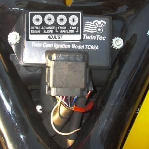 The TC88A Ignition Module is usable on the 2004-2006 carburetored models of the Sportsters. It replaces the stock Ignition Module and utilizes the CKP sensor and the MAP sensor to control the ignition timing.
The TC88A has dials on the module for selecting pre-programed ignition timing maps and choosing the level of the RPM Limiter. This is accomplished with two dials for timing maps and two dials for the RPM Limit.
One of the timing dials sets the Initial Timing while the second dial selects the Timing Advance Slope. These settings are explained further in the link below to information about the MAP Files.
One of the RPM Limit dials chooses the x1000 value and the other selects the x100 value. Note: Setting the RPM Limit to 0 will disable the module. (BE CAREFUL not to set the RPM Limit above a safe level for your engine configuration!)
In addition to the pre-programmed timing maps (selectable by the dials), the unit can be user-programmed to utilize customized timing advance maps instead of the pre-programmed maps. To use these customized maps, you must have a computer interface, such as the Daytona USB Interface (18014), and the Daytona PC-Link Software, to communicate with the TC88A module. (See the extra links below.)
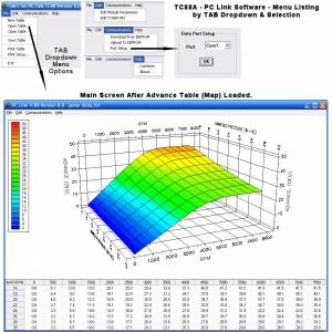
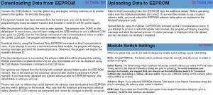
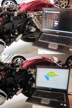
Screen Shots of the PC Link Software:
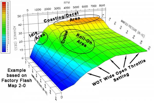
The TC88A map table will allow setting the spark timing for MAP conditions from 16 to 30 InHg using 2 InHg increments. Note that 30 InHg manifold pressure represents wide open throttle (WOT) and 16 InHg represents deceleration or idle conditions.
There's a rough correlation of the throttle position to certain areas of the map image. Also remember that the CV carb responds to throttle changes with changes in the slide (which is a variable venturi) - It is the combination of the two that creates the change in pressure. The general relationship is illustrated below:
A Few Comments From XLForum Members
As should all web information, these should be evaluated to determine their value & usability for your situation.
~ ~ ~ ~ ~ ~ ~ ~ ~ ~ ~ ~ ~ ~ ~ ~ ~ ~ ~ ~ ~ ~ ~ ~ ~
Be sure to read these comments:
Why Adjust The Spark Timing? by RacerWill
Too Much Advance Timing by Aaron Wilson
Manifold Absolute Pressure -vs- Vacuum Reading by RacerWill
Check out these XLForum Threads for additional information related to map files:
https://www.xlforum.net/forum/sportster-motorcycle-forum/sportster-motorcycle-electrical/sportster-motorcycle-electrical-and-ignition/94210-tc88a-and-rs-232-runtime-error?t=780755 - Rocketmangb - Discussing USB connections
https://www.xlforum.net/forum/sportster-motorcycle-forum/sportster-motorcycle-electrical/sportster-motorcycle-electrical-and-ignition/11396-final-tc88a-map-program-lots-of-other-data?t=18702 — Turbota - Final TC88A MAP program + lots of other data (200pg)
http://xlforum.net/forums/showthread.php?t=336441 – See Turbota's Comments in Post#10
https://www.xlforum.net/forum/sportster-motorcycle-forum/sportster-motorcycle-electrical/sportster-motorcycle-electrical-and-ignition/132607-tc-88a-chat?t=1419021 - Rico05r - TC 88A Chat
https://www.xlforum.net/forum/sportster-motorcycle-forum/sportster-motorcycle-electrical/sportster-motorcycle-electrical-and-ignition/132778-daytona-tc88a-do-your-own-mapping-tips-questions?t=1422868 - xena - Daytona TC88A Do your own Mapping, Tips, Questions
https://www.xlforum.net/forum/sportster-motorcycle-forum/sportster-motorcycle-electrical/sportster-motorcycle-electrical-and-ignition/194188-how-to-needed-tc88a-ignition-module-donated-to-me?t=2070390
https://www.xlforum.net/forum/sportster-motorcycle-forum/sportster-motorcycle-electrical/sportster-motorcycle-electrical-and-ignition/196442-1250-break-in-map-for-tc88a?t=2072970
https://www.xlforum.net/forum/sportster-motorcycle-forum/sportster-motorcycle-electrical/sportster-motorcycle-electrical-and-ignition/198510-tc88a-eeprom-or-flash?t=2075312
https://www.xlforum.net/forum/sportster-motorcycle-forum/sportster-motorcycle-electrical/sportster-motorcycle-electrical-and-ignition/190007-tc88a-maps?t=2026174
Some excerpts from these threads are here:
http://sportsterpedia.com/doku.php/techtalk:ref:engctl50f
Note: Early experimentation with the TC88A module may have produced maps with timing expectations different from the maps that were created later. However, as always, every engine wants and needs settings that are specific to that particular build configuration.
~ ~ ~ ~ ~ ~ ~ ~ ~ ~ ~ ~ ~ ~ ~ ~ ~ ~ ~ ~ ~ ~ ~ ~ ~
https://www.xlforum.net/forum/sportster-motorcycle-forum/sportster-motorcycle-electrical/sportster-motorcycle-electrical-and-ignition/132778-daytona-tc88a-do-your-own-mapping-tips-questions?t=1422868
Post#139 - Xena mentions this:
There is a free program that does show all the logged data
and it's pretty good, better than excel spreadsheet.
Graphically Evaluate Log Files:
http://www.efianalytics.com/MegaLogViewer/download
Table Data Files - '.tbl'
The TC88A PC-Link Software will allow you to upload customized ignition timing files into the module. These filenames end with a '.tbl', indicating they are Table Files (such as Jester_Delta.tbl). These files are actually text files and the PC-Link Software will put that data into the memory of the TC88A to cause it to respond according to your customized settings.
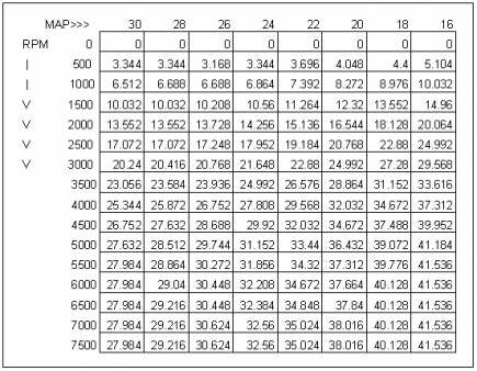
Here's a sample of what data is actually contained in the '.tbl' files (this is taken from the Jester_Delta.tbl file) :
Sample 'Jester_Delta' Table Diagram shown in PC-Link when that file is loaded. Here, MAP is vertical & RPM is horizontal.

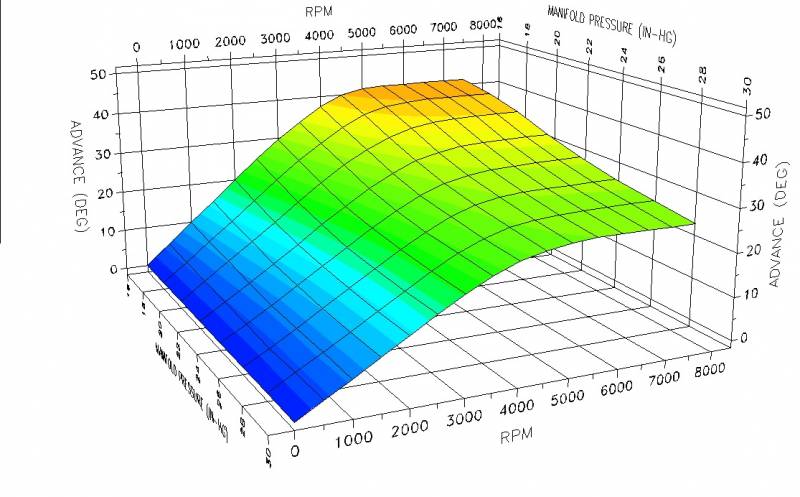
Below is the 3D Map that the TC88A PC-Link Software produces for the 'Jester Delta' table data. Please note that this type image view (because it is an angled view of 3D information) distorts the advance values at higher MAP levels (near 30 InHg). The image makes those advance values appear less than their actual values. So refer to the table data for a more accurate perception of the programmed advance value at the higher MAP levels.
'Jester Delta' represented by a 3D image:
Module Parameters
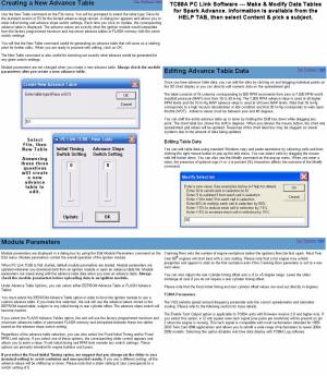
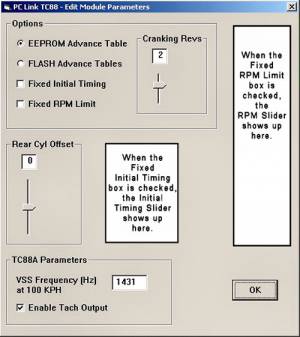 The module parameters (which are saved in the map TBL file) can be altered in the PC-Link software under OPTIONS. Be sure to carefully set these parameters BEFORE UPLOADING your customized map to the module and before saving your map for future use. AFTER the TBL information is uploaded to the module, these settings will be effective on the module.
Notice in the shown box (which represents the settings of the Jester_Delta.tbl file) that the Initial Timing Slider and RPM Slider are not there, because the check boxes for Fixed Initial Timing & Fixed RPM Limit are not checked.1))
Using the references as saved in the TBL file (shown above), the various module parameters under 'OPTIONS' are explained below:
SelEEPROMTblFlag:
If the EEPROM Advance Table is checked, this parameter is set TRUE - it indicates you are using a customized map stored in the EEPROM memory. When this is TRUE, it will DISABLE the ADVANCE SLOPE DIAL on the module since the pre-programmed maps are not being utilized.
If the FLASH Advance Tables is checked, this parameter is set FALSE - indicating you are not using a customized map but rather are using the pre-programmed FLASH Advance Tables and the Module Dials will be used to control the map selected.
FixedInitialTmgFlag:
InitialTiming:
If the Fixed Initial Timing box is checked, the FixedInitialTmgFlag is set TRUE and only then can you modify the Initial Timing Slider (ITS).
The ITS setting is a way to universally alter (increase or decrease) the advance timing values of the entire map without actually changing each individual value.
| Selecting 0 on the ITS is equivalent to selecting 5. In either case, the map data is utilized exactly as programmed in the table. Whatever value you select on the ITS will be uploaded to the module as part of the TBL data. |
|
| If you select 4, 3, 2 or 1 on the ITS, the map timing values will be reduced by 1° for each ITS value lower than 5. | If you select a value of 6, 7, 8 or 9 on the ITS, the map timing values will be increased by 1° for each ITS value higher than 5. |
| Selecting ITS Value of: .. 4 = -1° of advance across every table value. .. 3 = -2° of advance across every table value. .. 2 = -3° of advance across every table value. .. 1 = -4° of advance across every table value. | Selecting ITS Value of: .. 6 = +1° of advance across every table value. .. 7 = +2° of advance across every table value. .. 8 = +3° of advance across every table value. .. 9 = +4° of advance across every table value. |
When the FixedInitialTmgFlag is TRUE, this selection will DISABLE the INITIAL TIMING DIAL on the module since that value is now fixed in the software.
If the Fixed Initial Timing box is unchecked, the FixedInitialTmgFlag is SET FALSE and the (unseen) Initial Table Slider value is set to 0.
When FixedInitialTmgFlag is FALSE, the INITIAL TIMING DIAL on the module will be ENABLED and active. It will alter the timing values across the board either downward or upward according to the value selected (in same manner as programming the ITS above). As a SAFETY PRECAUTION, you should always set the INITIAL TIMING DIAL to 5 (same as 0) whenever a new map is loaded, which will utilize the map timing values as programmed. If you want the value of the advance timing (across the board) lowered from the map TBL value, set the DIAL at 4, 3, 2 or 1. If you want the values raised, select 6, 7, 8 or 9.
RearOffset:
It is sometimes advantageous to alter the timing of the rear cylinder relative to the front cylinder timing. This slider will allow you to select -5° to +5° of timing difference from the front cylinder setting.
FixedLimFlag:
RPMLimit:
If the Fixed RPM Limit box is checked, the FixedLimFlag is set TRUE and only then can you modify the RPM Limit Slider (RLS). The RLS is set to a RPM value as appropriate to your engine configuration (kept low for break-in periods). The slider will adjust from a low of 3000 RPMs to a high setting of 9900 RPMs. The module parameter in the TBL file (RPMLimit) will reflect the value chosen on the RLS.
When FixedLimFlag is TRUE, this selection will DISABLE the RPM LIMIT DIALS on the module since that value is now fixed in the software.
If the Fixed RPM Limit box is unchecked, the FixedLimFlag is set FALSE. This will allow the two RPM LIMIT DIALS on the module to control the limiter value. One DIAL selects the x1000 value and the other DIAL selects the x100 value. The nominal range of RPMs is 3000 to 9900. Note: Setting the RPM Limit below 3000 will equate to setting it at 3000 and not below that. Setting the RPM LIMIT DIALS to 0 (both DIALS at 0) will disable the module.
CrankRevs:
If the Cranking Revs Slider (CRS) is set to anything other than 0, it represents how many engine revolutions should occur before the first spark is produced. While the CRS is typically left at 0, it is sometimes advantageous for high compression engines to turn over once or twice before firing the plugs.
VSSFreq:
The ignition module receives pulses from the Vehicle Speed Sensor (VSS) which is triggered from the teeth on the 5th gear in the transmission. It must interpret these pulses based on transmission gearing and tire sizes to produce a valid value to send to the speedometer for speed and odometer readings.
An appropriate value must be entered in the VSS Frequency box to represent the frequency (in Hz / pulses per second) of the incoming signal that is produced when travelling 100KPH.
According to the Twin Tec manual, the typical values are: 2004-5 883 = 1431; 2004-5 1200 = 1386; 2006 883 = 1682; 2006 1200 = 1624.
TachEnableFlag:
If the Enable Tach Output box is checked, the TachEnableFlag will be SET TRUE. This setting will generate a 12v square wave on pin2 matching the RPM of the engine. This signal will be usable by most discrete signal tachometers (like those that connect off of the ignition coil). The output signal is one pulse per revolution. If this setting is utilized, the Real-time Data Display in the TC88A logging software will not function.
If the Enable Tach Output box is unchecked, the TachEnableFlag will be SET FALSE.
Operation of the Module Dials while using a customized map in the EEProm
See the discussion of the individual Module Parameters. Those settings affect whether the dials are active.
| Returning to FACTORY MAP FILES after having loaded a custom map - Enable using the Module Dials. If you want to return to using the module dials to select pre-programmed maps, you must switch from using the custom map to using the FLASH maps. You need to log-in to the PC-Link software and change the settings for the ignition module. In PC-Link, go under “Edit module parameters” and select “Flash Advanced Tables.” After you have uploaded that configuration to the ignition module, your dials on the front will become active. (according to Tech Support at Daytona Twin Tec 2)) |
Questions to be answered:
What data is saved in those first four lines in the TBL?
— Presumably: 'GRID 16 8' is the RPM/MAP TABLE dimensions
— Presumably: '500 1' is the value between RPM Points
(Most of the above info is from the 2015 Software Install Manual)
Helpful Resources at Daytona Twin Tec website:
=======================================
TC88A Product Page
Full Installation Manual - WORD DOC Format (12/2019)
PC-Link Software Download (ZIPPED)
TC88A Log Software (ZIPPED)
TC88A Wiring Diagram
Factory Ignition Map Files
| The TC88A comes with built-in Factory Flash Ignition Maps. They are accessible (without a computer) by using the map dials, labeled 'Initial Timing' and 'Advance Slope', on the module. The module comes from the factory with the 'SelEEPROMTblFlag' set to FALSE, which tells the module to use the Factory Flash Maps, selected by the module dials. Each dial can be set from 0 to 9, which provides a choice of 100 pre-programmed map configurations, by selecting a setting of 0-0 thru 9-9. We have made those files available for download, to examine or modify, however you think best. If you wish to access any of those files: CLICK HERE to reach that page. |
Customized Ignition Map Files - 1
| This is a list of the customized MAP Files created for specific engine modifications by Rico05r, Rocketmangb, Jester Motorwerkz: If you wish to access any of these files CLICK HERE to reach that page. 1682_VSS_3 25_15_Map_for_1250 883mapjakd Andrea-s_1250_Map-base basore_Map_for_1250 basore_Map_for_1250_2 Blue_Bitch_Table Greg_Map_2-0 Hybrid_2-0 Hybrid_2-0_883_Version jak_10-5 jak_2 jak_3 Jester_Delta Jester_Motorwerkz_88-90_Inch_Map_Generic_Mod_1 Jester_Motorwerkz_88-90_Inch_Map_Generic_VSS_05_1200 Jester_Motorwerkz_Moscow_Map Jester_Motorwerkz_Rocketman_01-15_Map Jester_Motorwerkz_Rocketman_03-15_Map Jester_Motorwerkz_Rocketman_04-15_Map Jester_Motorwerkz_Rocketman_04-28-2015_Map Jester_Motorwerkz_Rocketman_05-15_Map Jester_Motorwerkz_Rocketman_12-14_Map Jester_Motorwerkz_Scarecrow_Map Lenster_Rico_Hybrid_Map Lenster-s_Map MAP_Modified_33 MAP_Modified_35_Revised Necromancer_883_convert R-D_Map_0 R-D_Map_1 R-D_Map_2 | Rico-s_1212_1-1_1200_Gearing Rico-s_1212_1-1_883_gearing Rico-s_1250_Base_Map_1200_Gearing Rico-s_1250_Base_Map_883_Gearing Rico-s_1250_Map_4-1_1200_Gearing Rico-s_1250_Map_4-1_883_Gearing Rico-s_1250_Map_Smackie_Version Rico-s_1250_Map_Version4-0_883_Gearing Rico-s_221_Map Rico-s_88inch_Map_1-0 Rico-s_88inch_Map_1-1 Rico-s_Hybrid_2-1 Rico-s_Hybrid_2-2 Rico-s_Hybrid_2-2_883 Rico-s_Jester_8_Ball_Capo_Map_06_1200_0 Rico-s_Jester_8_Ball_Capo_Map_06_1200_1 Rico-s_Jester_III_Map_Wedge_Mod Rico-s_Jester_III_Map_Wedge_Mod_1 Rico-s_Jester_III_Map_Wedge_Mod_2 Rico-s_Jester_IV_Map Rico-s_Jester_IV_Map_06_1200_0 Rico-s_Jester_IV_Map_06_1200_1 Rico-s_Jester_IV_Map_VSS_1475 Rico-s_Jester_Motorwerkz_Map_for_Andrea_06_883_Gearing Rico-s_Jester_V_Map_04-05_1200 Rico-s_Jester_V_Map_04-05_883 Rico-s_Jester_VII_Map_VSS_04-05_883 Rico-s_Jester_VII_Map_VSS_06_883 Rico-s_King_Jester_Map_0 Rico-s_King_Jester_Map_1 Rico-s_Voodoo_Map_06_1200 RTM-Andrea_1250_Map_ base-1431_2 RTM-Andrea_1250_Map_AGGRESSIVE_Version_4-1 RTM-Andrea_1250_Map_AGGRESSIVE-1431_2_Rev-3 RTM-Andrea_1250_Map_Revised_aggressive RTM-Andrea_1250_Map_Revised-aggressive-VSS_1630 RTM-Andrea_1250_Map_Version_4-0_revised_ramp_from_0to45 Scarecrow_1682 SE_COPY_SORTA WEDGE_Mod_1682 WTF_Map_12-29-2014 |
Customized Ignition Map Files - 2
This is a list of the customized MAP Files created for specific engine configurations by various
XLForum Members (or others). Be sure to read the included (txt) file to understand the engine
configuration for which the map was created.
| If you wish to access any of these files CLICK HERE to reach that page. | Gunner60-1 (Hammer1250 - XBheads - JH570cams - 10:1comp) |

