Table of Contents
This is an old revision of the document!

REF: General-MSR 04
Using / Diagnosing with a Slack Tube (Manometer)
See also in the Sportsterpedia:
- Manometer (slack tube) for Measuring Air Pressure (what it is and how it works)
Pressure measurements given in inches or millimeters of water / mercury / other liquid are based on the earliest instrument developed for measuring pressure, the liquid column gauge or manometer (AKA slack tube). 1)
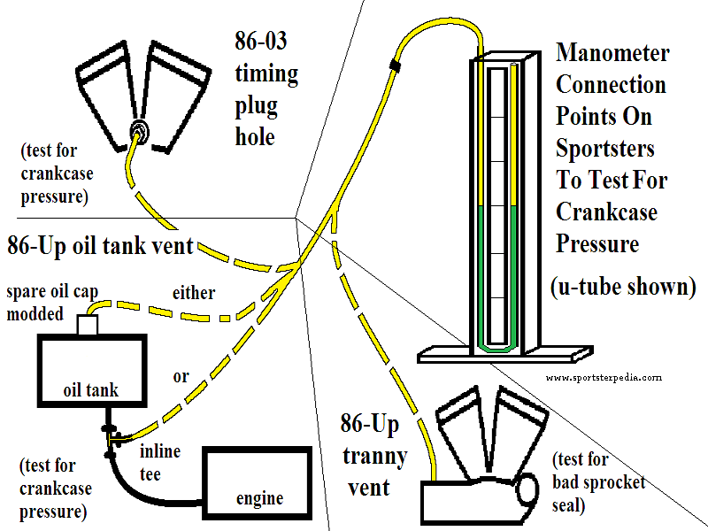
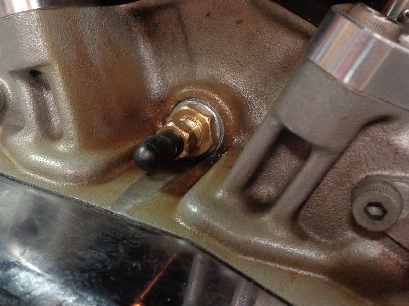
Where to Connect to the Engine
| 1986-Present manometer connections. 2) |
 |
Valve vs No Valve on Source Outlet
A valve is sometimes used on the source outlet to connect the test line to the manometer.
This is a safety precaution in case more vacuum is being pulled than the manometer is calibrated for.
Example, the water level in the right leg of a U-tube manometer cannot be allowed to go down past the “U” in the bottom of the tool.
If this happens, all of the water will be sucked inside the engine from there.
If you have a 3 foot tall manometer and are only measuring 1 PSI or less air pressure, no valve will be needed.
However, if the source is pulling 1-1/2“ or more of vacuum, the water will be sucked into the engine unless the manometer is taller.
A taller height of water column increases the air pressure it can measure.
See the chart below for pressure conversions.
If you are unsure about the amount of vacuum the engine is running, it may be best to buy a gauge that measures in In Hg or use a taller manometer.
Or, you can install a valve on the source outlet to throttle (control) the air pressure that goes to the manometer.
The ID of the valve needs to be no less than the ID of the source outlet (1/4” outlet needs a 1/4“ or higher ID valve).
You can pinch off the clear hose with your fingers, start the engine and gradually let go of the hose to see if the water is going to back feed into the engine.
That way you'll know for sure if you need a valve or not.
Timing Hole Plug (57-03)
- This method won't work on 04-up models as they have no timing hole plug.
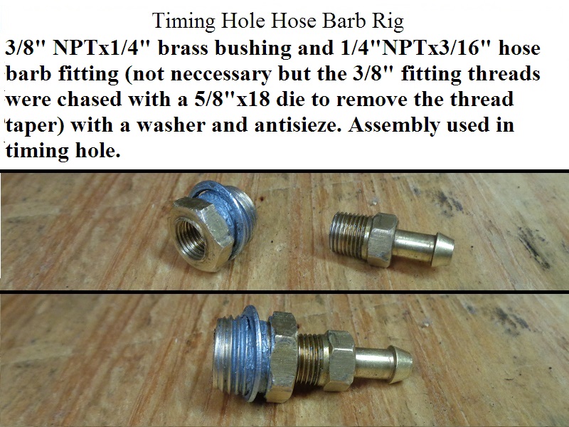
Basically you need some clear vinyl hose and a nipple fitting to replace the timing hole plug.- 1957-2003 engines have a timing plug hole that can be removed and a couple fittings with a hose barb end can be installed to accept the hose.
- The timing hole threads are standard 5/8”x18. The threads on a 3/8“ NPT fitting are about 5/8”x18 also.
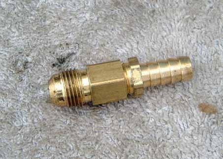
A 3/8” flare to 1/4“ FPT fitting with a 1/4” MPT to 3/8“ hose barb will work.
So will a 3/8“ NPT x 1/4” NPT bushing and a 1/4“ NPT to 1/8” or 1/4“ hose barb assembly (depending on what size hose you are using).
| Timing hole plug fittings | ||
| 3/8” flare to 1/4“ FPT fitting with a 1/4” MPT to 3/8“ hose barb. 3) | 3/8” NPT x 1/4“ NPT bushing and a 1/4” NPT to 3/16“ hose barb fiting. 4) | |
 |  | 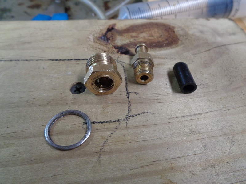 |
| Fitting installed (just snugged up) with clear hose and a homemade manometer. 5) | ||
 |  | 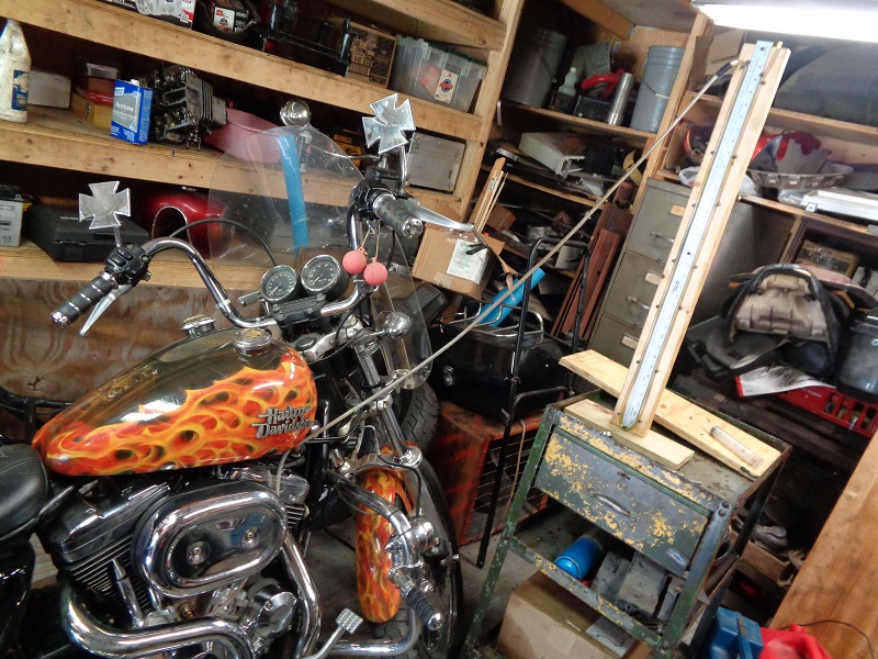 |
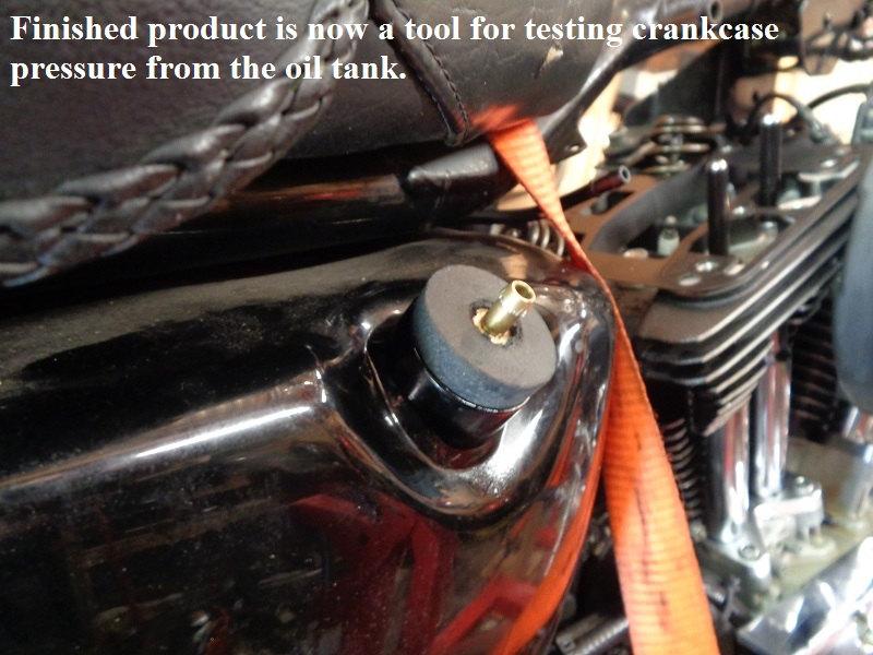
Oil Tank / Vent Line
You can test crankcase pressure from the tank vent as it will show the amount of vacuum that is being created between the cam chest and the oil tank.
This measurement (when tested on a 2001 XL1200S) was lower than when the same engine was tested from the crankcase.
And the pressure swings was lower in the tank than in the crankcase (extreme highs from vacuum to air pressure).
See the full article, Testing with a Slack Tube (Manometer) by bustert, in the Sportsterpedia.
An inline tee fitting can be installed in the (oil tank to cam chest) vent line for use as a testing tap point.
You can cut the hose and install the tee and with band clamps.
Or you can remove the hose, install one straight end of the tee there, the other end connects to the tank via a short hose piece (with band clamps).
Or you can modify a spare oil tank cap with a hose barb fitting.
Make sure the test hose stays above the tee / fitting at all times to keep oil from dripping / draining into the test hose.
The results below are in (inches of water) but remember, you have to add both sides.
So a 15” rise on one side with a 15“ decrease on the other would be 30” of water column total.
These tests were done from both the crankcase and the oil tank.
The crankcase was tested from the timing plug and the oil tank was tested with a modded spare oil cap.
So the pics on the right represent actual working pressure in the tank.
| Slack Tube testing from timing hole plug. 6) | Slack Tube testing from oil tank | ||
| 1000 RPM |  | 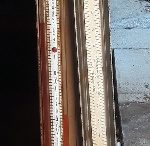 | 1000 RPM |
| 6000 RPM | 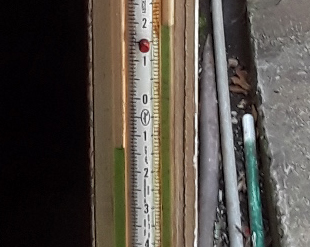 |  | 6000 RPM |
Modified Oil Tank Cap
You can drill a hole for an NPT fitting in a spare oil cap or make a cap just for testing.
The one below was made from a rubber plug bought at Lowes. Click here to see the pics of the mod.
If you're testing the 04-up plastic oil tank for high pressure, the oil cap is not going to be helpful as a test point.
You need a tee installed in the vent line for that.
Testing crankcase pressure
- Connect the left side of the manometer tube to the test port (not the engine breather vents - leave these intact)
Possible test points can be the timing inspection hole or a tee installed into the oil tank vent line.
The line from the engine / oil tank doesn't have to be clear but a clear line will show any oil mist that escapes but not far out enough to reach the meter.
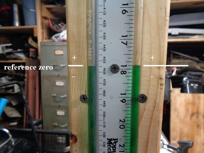
Allow the liquid to stop moving in the U-tube before measuring. - Note the beginning point before the meter was hooked to the engine.
The level should be the same on both tube legs. This is noted as the established zero point or (zero reference).
A U-tube manometer may need to be wedged under one end to establish a true level across both sides of the manometer. - Crank the engine (make sure it's at operating temperature or the readings will not be accurate).
- Record the height of the liquid in the tube (left or right) with the tallest amount..
If the liquid is higher in the left tube, the pressure is negative. If the liquid is higher in the right tube, the pressure is positive. - Calculate Inches of Water Column
- Add / subtract the distance of change between the liquid's current level on either side and it's zero reference point.
- Multiply this distance x 2 since the surface of the liquid on the one side goes down by the same distance on the opposite side.
(the total distance the liquid moved is twice the measured movement of either one side) - Convert metric measurements to inches if needed.
- The result is expressed as the pressure in Inches of Water Column.
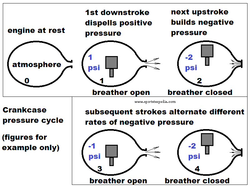
At idle gives the most vacuum in the crankcase you'll have throughout the RPM range.
The first downstroke expells positive pressure from the downstroke. The next upstroke pulls a slight vacuum.
You'll see this happen in the hose.
The next downstroke pushes positive pressure which lowers the vacuum but not enough to turn the crankcase to a positive charge.
This cycle retains a “slight variable vacuum” in the crankcase at idle.
As RPM is raised, the water level will lower slightly in the left leg and rise in the right leg.
| This drawing examples the breathing cycle. 8) |
 |
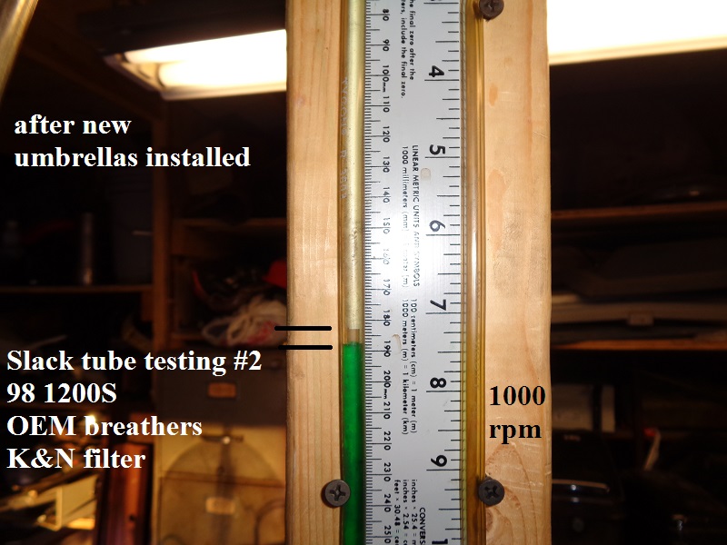
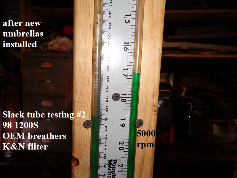
In the example below, “reference zero” was set at app. 17-7/8“ using a homemade slack tube.
- At hot idle (1000 RPM), the engine was exerting negative (vacuum) pressure with water rising in the left leg to app. 7-3/8”.
(which is app a 10-1/2“ rise (or a vacuum pressure of 21” of water column)
- At 5000 RPM, the engine was exerting a positive pressure with water rising in the right leg to app. 17“.
(which is app. a 7/8” rise (or a positive pressure of 1-3/4“ of water column)
Conversion Chart
Conversion Results Rounded:
Click here 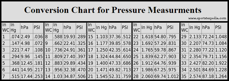 to open a picture of the chart. 12)
Conversion Chart for Pressure Measurements:
| In WC | In Hg | hPa | PSI | In WC | In Hg | hPa | PSI | In WC | In Hg | hPa | PSI | In WC | In Hg | hPa | PSI | In WC | In Hg | hPa | PSI | ||||
| 1 | .074 | 2.49 | .036 | 8 | .588 | 19.93 | .289 | 15 | 1.103 | 37.36 | .512 | 22 | 1.618 | 54.80 | .795 | 29 | 2.133 | 72.24 | 1.048 | ||||
| 2 | .147 | 4.98 | .072 | 9 | .662 | 22.41 | .325 | 16 | 1.177 | 39.85 | .578 | 23 | 1.692 | 57.29 | .831 | 30 | 2.207 | 74.73 | 1.084 | ||||
| 3 | .221 | 7.47 | .108 | 10 | .736 | 24.91 | .361 | 17 | 1.250 | 42.35 | .614 | 24 | 1.765 | 59.78 | .867 | 31 | 2.280 | 77.22 | 1.120 | ||||
| 4 | .294 | 9.96 | .145 | 11 | .809 | 27.40 | .397 | 18 | 1.324 | 44.84 | .650 | 25 | 1.839 | 62.27 | .903 | 32 | 2.354 | 79.71 | 1.156 | ||||
| 5 | .368 | 12.45 | .181 | 12 | .883 | 29.89 | .434 | 19 | 1.400 | 47.33 | .686 | 26 | 1.912 | 64.76 | .939 | 33 | 2.427 | 82.20 | 1.922 | ||||
| 6 | .441 | 14.95 | .217 | 13 | .956 | 32.38 | .470 | 20 | 1.471 | 49.82 | .713 | 27 | 1.986 | 67.25 | .975 | 34 | 2.501 | 84.69 | 1.228 | ||||
| 7 | .515 | 17.44 | .253 | 14 | 1.03 | 34.87 | .506 | 21 | 1.545 | 52.31 | .759 | 28 | 2.060 | 69.74 | 1.012 | 35 | 2.574 | 87.18 | 1.264 |
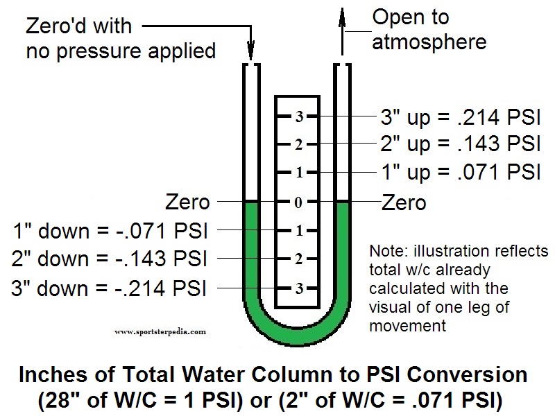
Calculating Between PSI and Inches of Water
The standard conversion from PSI to Inches of Water: 1 PSI is equal to 28“ of water column (overall vertical movement).
When using a U-tube type manometer, divide the total inches of water travel (in both legs) by 2 as the water in each leg of the instrument are moving.
I.E., 1” down on one leg and 1“ up on the other equals a total of 2” of total movement.
Therefore, 1 PSI = 28“ of water divided by 2 = 14” of movement per leg per pound of pressure.
- Example: To Convert PSI to Total Inches of Water:
- 4 psi = 112“ of water (4 x 28 = 112)
- Likewise: To Convert Total Inches of Water to PSI:
- 112” of total water = 4 PSI (112 / 28)
- In the crankcase pressure test subject above:
- At idle, the mean vacuum pressure is -0.75 PSI (21“ of total water column / 28)
- At 5000 RPM, the mean positive pressure is +0.0625 PSI (1.75” of total water column / 28)
Inches of Water to Inches of Mercury (Hg)
1“ of water column = 0.073555905223332” in Hg.
Calculating Pascal Units
The formula for calculating the source pressure is PD = P G H.
Pd = the pressure difference.
P = the density of the liquid in the manometer: mercury equals 13,590 kg/m3 and water equals 1,000 kg/m3.
G = acceleration of gravity: 9.81 m/s2.
H = the height of the liquid in meters.
- Note the beginning point before the meter was hooked to the engine.
The level should be the same on both tube legs. This is noted as the established zero point or (zero reference). - Measure the distance between the liquid's current level on one side and it's zero reference point.
Multiply this distance by 2 since the surface of the liquid on the right goes down by the same distance that the left side goes up.
The total distance the liquid moved is twice the measured movement of one side.
The result is the pressure in water inches. - Convert the non-metric measurements to metric ones. Then, convert the manometer reading to standard units of pressure.
- Use the standard formula p = d * h * 9.8.
“P” is the pressure in pascals.
“D” is the density of the liquid in the tube in kilograms per cubic meter.
“H” is the doubled height difference in meters from step 2.
9.8 is the downward force of gravity, 9.8 meters per second squared.
So if you measure a height difference of .01 meters, double it to .02, multiply by 1,000 kg per cubic meter for water and multiply by 9.8 to get 196 pascals of pressure.
The calculation in step 4 above gives a gauge pressure that is relative to normal atmospheric pressure. 14)
When one side of the tube is open and the liquid is at the same level on both sides, the pressure on the connected side is standard atmospheric pressure.
(14.7 psi or 101.325 kilopacals at sea level)
To determine absolute pressure, you must add standard pressure to your results.
For the above example, the positive pressure of 196 pascals is 196 + 101,325 = 101,521 pascals of absolute pressure.
If your elevation is substantially higher or lower than sea level, get a barometer reading and use its indicated pressure instead of 101.325 kilopascals.
Glossary
Some common terms. 15)
Absolute Pressure.
A measurement referenced to zero pressure; equals the sum of gauge pressure and atmospheric pressure.
Common units are pounds per square inch (psia), millimeters mercury (mmHga), and inches mercury (in.Hga).
Accuracy.
A measure of the closeness of agreement of a reading to that of a standard.
For absolute accuracy, compare to a primary standard (one recognized by NIST).
Accuracies are usually specified as a plus or minus percent of full scale.
Calibration accuracies are often given as plus or minus percent of reading with plus or minus counts.
Ambient Pressure.
The pressure of the medium surrounding a device.
It varies from 29.92 in.Hg at sea level to a few inches at high altitudes.
Atmospheric Pressure.
The pressure of the atmosphere on a unit surface (also called barometric pressure). At sea level, it is 29.92 in.Hg absolute.
Count.
The smallest increment of an A/D conversion that is displayed.
Differential Pressure.
The difference between two measurement points. Common units are inches of water (in.H2O), pounds per square inch (psi), and millibars (mbar).
Display Resolution.
The maximum number of digits on a digital display.
For example, a display resolution of 4½ digits reads a maximum of 19,999 counts; and a display resolution of 5 significant digits reads a maximum of 99,999 counts.
Gauge Pressure.
A measurement referenced to atmospheric pressure. It varies with the barometric reading.
Also used to specify the maximum pressure rating of manometers. Common units include pounds per square inch (psig).
Range.
The region between the lower and upper limits of measurements.
Resolution.
The smallest portion of a measurement that can be detected.
Sensitivity.
The smallest change in measurement that can be detected.
Uncertainty.
An estimate of the possible error in a measurement. This is the opposite of accuracy.
Vacuum.
Any pressure below atmospheric pressure.
When referenced to the atmosphere, it is called a vacuum (or negative gauge) measurement.
When referenced to zero pressure, it is an absolute pressure measurement.
Zero Absolute Pressure.
The complete absence of any gas; a perfect vacuum.