Table of Contents
This is an old revision of the document!

EVO: Electrical System
FUSES, RELAYS, CHARGING SYSTEM
Be sure to review the basic Electrical Concepts in the Reference Section, especially wire gauging.
See also Current Draw with Key Switch OFF
The Circuit Breakers (CB) used on Sportsters are of the self-resetting type. Once they break contact, they will automatically reset after a period of time. These breakers function based on a bi-metallic strip that is heated by current flowing through the strip. More current will cause more heat.
If the rated amperage for the CB is exceeded, the strip will be overheated, causing it to bend away from the internal contact, thereby opening the circuit and removing the current flow. Once the bi-metallic strip has cooled sufficiently, it will return from its heated position and once again make contact. This will allow the current to begin flowing again. If the circuit is still drawing excessive current, the CB will repeat the open & close cycling until the current level is reduced below the current rating and no longer causing the bi-metallic strip to overheat.
Although very reliable, over time & usage, the CB may no longer function at the rated current, requiring replacement of the Circuit Breaker.
Starting in 1998, the individual circuits were protected with fuses (rather than circuit breakers), while the overall system was still protected with a self-resetting circuit breaker. In 2004, the overall system protection was implemented with a Maxi-Fuse.
The following quotation makes the point that fuses are often slow to react to overcurrent situations. It is critical to replace rated fuses with the same rating in order to properly protect the circuits.
First, fuse ratings can be a bit misleading. A 10A ATO (automotive) fuse will conduct 11 amps for 100 hours minimum. At 13.5 Amps a 10A ATO fuse can take as long as 10 minutes to blow. It is not like once you draw 10 amps “poof” the fuse is gone. (From FUSE SIZING PRIMER located at http://www.powerlet.com/learningCenter/fuseSizing)
Fuses/Circuit Breakers
(1984L-1990)
- All 1986 to 1990 models have 4 circuit breakers mounted on the front side of the rear fender under the seat. 1)
- Circuit Breakers (CB) - Under Seat - Automatically Resettable - Ring Lugs for wiring
- 30A - Main Circuit Breaker
- Keyswitch
- 'Ignition' position (White Wire) runs to Ignition & Accessories CBs
- 'Lights' position (Green Wire) runs to Lights CB
- Both Keyswitch positions feed all CBs because of jumper between Ig & L at Keyswitch
- Circuit Breaker Ratings
- 15A - Lights CB
- 15A - Ignition CB
- 15A - Accessories CB


(1991-1993) 2)
- All 1991 to 1993 models have 4 circuit breakers mounted on the front side of the rear fender under the seat. 3)
- Circuit Breakers (CB) - Under Seat - Automatically Resettable - Ring Lugs for wiring
- 30A - Main Circuit Breaker
- Keyswitch
- 'Ignition' position (White Wire) runs to Ignition & Accessories CBs
- 'Lights' position (Green Wire) runs to Lights CB
- Both Keyswitch positions feed all CBs because of jumper between Ig & L at Keyswitch and buss bar at CBs
- The 4-way Flashers are activated from the 'Accessory' position by pressing both turn signal switches at the same time - Flashers will operate this way until the battery is dead or the keyswitch is turned off
- Circuit Breaker Ratings
- 15A - Lights CB
- 15A - Ignition CB
- 15A - Accessories CB
(1994-1997)
- All 1994 to 1997 models have 5 circuit breakers mounted under the seat. Ignition, instruments, lights and accessories are mounted on the circuit breaker block installed in the electrical bracket under the seat. The main circuit breaker is mounted on the electrical bracket on the right side of the circuit breaker block.4)
- Circuit Breakers (CB) - Automatically Resettable
- 50A - Main Circuit Breaker (1994-1996)
- 30A - Main Circuit Breaker (1997)
- Keyswitch
- 'Accessory' position allows 4-way Flasher without other Lights active
- 'Accessory' position (Green Wire) runs to Accessories CB (also active with Ignition position)
- 'Ignition' position (White Wire) runs to Ignition, Instruments and Lights CBs
- The 4-way Flashers are activated from the 'Accessory' position by pressing both turn signal switches at the same time - Flashers will operate this way until the battery is dead or the keyswitch is turned off
- Circuit Breaker Ratings
- 15A - Ignition CB
- 10A - Instruments CB
- 10A - Lights CB
- 15A - AccessoriesCB
 (1998-2003)
- These models have a Main Circuit Breaker, 4 Fuses, the Starter Relay and the Data Link Connector (1200S Only) located under left-side triangle cover to rear of battery.
- Fuses - Socketed and individually insertable
- 30A - Main Circuit Breaker
- Keyswitch
- 'Accessory' position allows 4-way Flasher without other Lights active
- 'Accessory' position (Red/Green Wire) runs to Accessories Fuse (also active with Ignition position)
- 'Ignition' position (Red/Black Wire) runs to Ignition, Instruments and Lights Fuses
- The 4-way Flashers are activated from the 'Accessory' position by pressing both turn signal switches at the same time - Flashers will operate this way until the battery is dead or the keyswitch is turned off
- Fuse Ratings
- 15A - Ignition Fuse
- 15A - Instruments Fuse
- 15A - Lights Fuse
- 15A - Accessories Fuse
(2004-2006)
- Fuses - Socketed and individually insertable - Fuse Panel under left side panel behind battery
- 30A - MaxiFuse - Socketed and insertable - At Battery
- Keyswitch
- 'Accessory' position (Red/Green Wire) also active in Ignition position
- 'Ignition' position (Red/Black Wire)
- The 4-way Flashers are activated from the 'Ignition' position (with the RUN switch on) by pressing both turn signal switches at the same time - The key can then be turned off & removed - Flashers will operate for up to 2 hours, then automatically shutdown
- Fuse Ratings
- 15A - Accessories Fuse (KeySw-Red/Green)
- 15A - Battery Fuse (Red wire from MaxiFuse direct)
- 15A - Lights Fuse (KeySw-Red/Black)
- 15A - Ignition Fuse (KeySw-Red/Black)
- 15A - Instruments Fuse (KeySw-Red/Black)
- 15A - Spare Socket (Unconnected)
(2007-2009)
- Fuses - Socketed and individually insertable - Fuse Panel
- 30A - MaxiFuse - Socketed and insertable - By Battery
- Keyswitch
- 'Accessory' position (Red/Gray Wire) also active in Ignition position
- 'Ignition' position (Black/Red Wire)
- The 4-way Flashers are activated from the 'Ignition' position (with the RUN switch on) by pressing both turn signal switches at the same time - The key can then be turned off & removed - Flashers will operate for up to 2 hours, then automatically shutdown
- Fuse Ratings
- 15A - ECM Fuse (Red wire from MaxiFuse direct)
- 15A - Fuel Pump Fuse (Yellow/Green wire from System Relay)
- 15A - Spare Socket - Unconnected
- 15A - Ignition Fuse (KeySw-Black/Red)
- 15A - Instruments Fuse (KeySw-Black/Red)
- 15A - Spare Socket - Unconnected
- 15A - Accessories Fuse (KeySw-Red/Gray)
- 15A - Battery Fuse (Red wire from MaxiFuse direct)
- 15A - Lights Fuse (KeySw-Black/Red)
- 15A – P&A Ignition Fuse (KeySw-Black/Red)
- 15A - Spare Socket (Unconnected)
- … - Open Socket
- NOTE: The 2007-2009 model years have a significant history of corrosion and gunk collecting in the fuse/relay tray causing low-grade shorts and erratic electrical operation - This is especially problematic if the bike is left outside or operated in the rain. It's a good idea to check & thoroughly clean this tray at least every year (or 4 to 6 months if parked outside).
(2010-2013)
- Fuses - Socketed and individually insertable - Fuse Panel
- 30A - MaxiFuse - Socketed and insertable - By Battery
- Keyswitch
- 'Accessory' position (Red/Gray Wire) also active in Ignition position
- 'Ignition' position (Red/Black Wire)
- The 4-way Flashers are activated from the 'Ignition' position (with the RUN switch on) by pressing both turn signal switches at the same time - The key can then be turned off & removed - Flashers will operate for up to 2 hours, then automatically shutdown
- Fuse Ratings
- 15A - Ignition Fuse (KeySw-Red/Black)
- 15A - Lights Fuse (KeySw-Red/Black)
- 15A - Accessories Fuse (KeySw-Red/Gray)
- 15A - ECM Fuse (Red wire from MaxiFuse direct)
- 15A - Battery Fuse (Red wire from MaxiFuse direct)
- 15A - Spare Socket (Unconnected)
(2014-????)
- 2014 - First Year of BCM (Body Control Module) for direct electrical control (minimizes fuses & eliminates relays)
- Fuses - Socketed and individually insertable - All fuses on Fuse Panel Cable (Near Battery)
- 40A - MaxiFuse - Socketed and insertable
- Keyswitch - Multilevel voltages using only two wires - Black/Green is Ground - Blue/White is signal to BCM
- 'Accessory' position provides a 'semi-Hi' signal on the Blue/White wire (using 800 ohms to ground)
- 'Ignition' position provides a 'Lo' signal on the Blue/White wire (using 200 ohms to ground)
- 'Off' position provides 'no load Hi' signal on the Blue/White wire (using no connection to ground)
- The 4-way Flashers are activated from the 'Ignition' position (with the RUN switch on) by pressing the triangle switch above the starter switch - The key can then be turned off & removed - Flashers will operate for up to 2 hours, then automatically shutdown
- Fuse Ratings
- 15A - Battery Fuse - ATO-type
- 15A - P&A Fuse - ATO-type
Relays
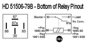
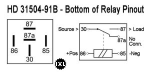
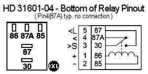
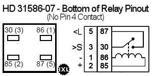
| NOTE - all diagrams are of the bottom of the relay. If you are checking for connections at the socket, the pin locations are the mirror reverse of the view here (of the bottom of the relay!) Left is right & right is left! |
(Be sure to see the note at the end of this section regarding diodes in relays)
(1975-1979)
- Starter Relay is auto type, two-bolt frame mount, ring lug for wire mounting
- HD 71463-73A
- NAPA MPE ST404SB
- NAPA ECH ST404
(1980-1992 & Early 1993)
- Starter Relay is single-bolt lug mount, connectorized
- Under the seat, on frame by the circuit breakers
- HD 31506-79B
 6)
6) - NAPA ECH MC23010
- Standard MC-RLY2
- Tyco V23234C1001X008
- Bosch 0332019151

(1994-2003 & Late 1993)
- Starter Relay is single-bolt lug mount, connectorized
- L93-97 - under the seat, on the circuit breakers mounting frame
- 98-03 - under left-side triangle cover to rear of battery
- HD 31504-91B
 7)
7) - NAPA ECH MC23013
- Standard MC-RLY4

(2004-2009)
- Starter Relay in 2004 became plug-in on Fuse Panel
- System Relay was added in 2007 as plug-in on Fuse Panel
- Both Relays are interchangeable (especially for diagnostics)
- HD 31601-04
 8)
8) - Possible Alternatives:
- NAPA ECH AR614
- Standard MC-RLY8
- Borg Warner R3154
- Niehoff RL 35381
- Gp Sorenson 41-5154
- OMRON G8H-UA-007401
- NOTE: The 2007-2009 model years have a significant history of corrosion and gunk collecting in the fuse/relay tray causing low-grade shorts and erratic electrical operation - This is especially problematic if the bike is left outside or operated in the rain. It's a good idea to check & thoroughly clean this tray at least every year (or 4 to 6 months if parked outside).

(2010-2013)
- Both Starter & System Relays are interchangeable (especially for diagnostics)
- HD 31586-07
 9)
9) - Possible Alternatives:
- Standard MC-RLY9
- (Superceded from: 31579-04)

(2014-on)
- Body Control Module (BCM) expanded capability - Eliminated relays (minimized fuses)
- 69992-12B BCM w/o Security
- 69994-12B BCM w/Security
NOTE: Polarity & Diodes
(This document may be of interest: http://www.autoshop101.com/forms/hweb2.pdf)
BATTERIES
Stock battery P/N is listed in the table below.
| Years | OEM Battery P/N | CCA | Ah | Type | …….. | Generic P/N | L/W/H | Wt |
|---|---|---|---|---|---|---|---|---|
| 79-96 | 65991-82B | 280 | 20 | AGM | Deka EXT16 - 325CCA - 19Ah | 6-7/8 x 4 x 6-1/8 | 17-lbs | |
| 97-03 | 65989-97A | 275 | 19 | AGM | Deka EXT20L - 310CCA - 17.5Ah | 6-7/8 x 3-7/16 x 6-1/8 | 15-lbs | |
| 04+ | 65958-04B | 205 | 12 | AGM | Deka EXT14L - 220CCA - 12Ah | 5-7/8 x 3-7/16 x 5-3/4 | 11.5-lbs |
The 'L' designation for the generic battery P/N is indicative of the grounding post of the battery - meaning that L version batteries (with the terminal side closest to you) have the grounding post on the left. Non-L versions have the grounding post on the right.
Check the 'fully charged' battery voltage levels.
And see the Reference Section for additional battery information.
CHARGING SYSTEM
The Sportster Charging System consists of the Alternator (Stator & Rotor), Regulator & Battery. The Alternator is of the Permanent Magnet type, the Regulator is a combination rectifier, shunt voltage regulator & the battery is typically of the Absorbent Glass Mat type.
Alternator Design
 The Sportster Alternator utilizes a stator & rotor. The stator is a series of electrical coils arranged in a radial pattern and the rotor has a sequence of permanent magnets mounted to a steel shell. The Alternator produces a single-phased AC output.
On 1986-1990 (4-speed) models, the Alternator is implemented in the primary drive cavity as part of the Clutch Assembly. In 1991 (5-speed models), the Alternator was moved to the Engine Sprocket Shaft in the primary drive cavity. As a small benefit in this later design, the weight of the rotating mass of the rotor/magnets supplements the centrifugal force of the crankshaft’s flywheel. The functional operation of the Alternator remained the same.
The rotor, with permanent magnets, rotates around the stator which has the stationary electrical coils. As the rotor magnets spin past the coils, they induce a current in the stator’s coils, called electromagnetic induction. Because the poles of the magnet are oriented north-south, the current reverses itself each time a magnet sweeps through its field, creating an alternating current.
The picture shown is similar to the 2000 models. There are a number of variations in specific part numbers over the years & models, although the basic design is the same for all 1991-later models.
The two-wire connector used for the Stator output needs to be compatible with the Regulator input connector. See the pictures of the input connectors for various model years in the Regulator section below. The stator output connectors will be similarly designed.
| Stator | Regulator | Rotor | Notes | Stator Specs | Regulator Specs | |||
|---|---|---|---|---|---|---|---|---|
| 4-Speed | Output Voltage | Coil Resistance | Output Voltage @75° | Current @3600rpm | ||||
| 1986-1990 | 29967-84C | 74523-84A | 36791-84 | Rotor+ClutchShell | 12v-18v AC/1000rpm | 0.2-0.4 Ohms | 13.8v-15.0v DC | 19 Amps |
| 5-Speed | ||||||||
| 1991-only | 29967-89C | 74523-91 | 32413-89C | Rotor Only | 19v-26v AC/1000rpm | 0.2-0.4 Ohms | 14.3v-14.7v DC | 22 Amps |
| 1992-1993 | 29967-89C | 74523-92A | 32413-89C | Rotor Only | ||||
| 1994-2003 | 29967-89C | 74523-94A | 32413-92C | Rotor Only | ||||
| 2004-2006 | 29967-89C | 74523-04 | 32494-04B | Rotor+EngSprocket | ||||
| 2007-2008 | 29900067 | 74546-07A | 32494-04B | Rotor+EngSprocket | 20v-28v AC/1000rpm | 0.1-0.3 Ohms | 14.3v-14.7v DC | 32 Amps |
| 2009-2013 | 29900067 | 74711-08 | 32494-04B | Rotor+EngSprocket | ||||
| 2014-2018 | 29900068 | 74700012 | 32494-04B | Rotor+EngSprocket | ||||
Take Note: The charging system is designed to keep the battery charged and supply power to run the bike. However, even if you disconnect the regulator from the system (and/or the stator from the regulator), the bike will run just fine on the battery alone. Without being recharged, the battery will slowly discharge to the point the bike will fail to run.
The run-time on the battery alone is surprising. If your stator or regulator fails while on a long-distance run, you can recharge the battery (wherever possible) and then run on it alone. To do so, you should minimize the current draw from unnecessary components by removing the fuses to those component circuits (such as lights). Of course, running in daylight with other riders is a safer situation in an emergency.10)
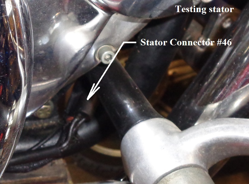
Basic Stator (Alternator) Test
Checking for Shorts
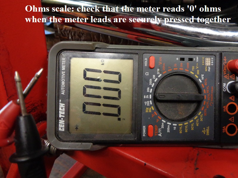
 Pull the connector between the Stator & Regulator, 2-pin connector near the regulator. Use a multimeter set to the Ohms Scale to measure resistance for these tests. (Before checking resistance, always check that the meter reads '0' ohms when the meter leads are securely pressed together. If the meter reads any value above zero, subtract this value from any resistance readings you take.)
1) Measure Resistance between the two Stator Pins (should be 0.2 - 0.4 Ohms)
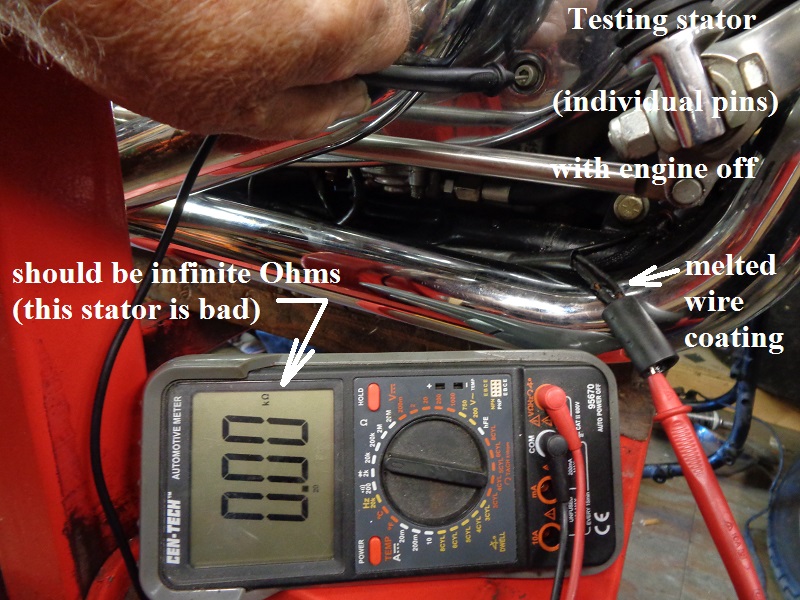
2) Measure Resistance from each Stator Pin to Ground (should be infinite Ohms)
Checking for Sufficient Voltage Production
With the Regulator still unplugged from the Stator:
Start the engine & run at approximately 2000 RPMs
(Set your multimeter on AC Volts - 100v Scale)
3) Measure AC Volts produced between the two Stator Pins (see the chart above for the expected voltages) 11)
Shut down the engine - Reconnect the Regulator - (Be sure to do voltage & ground checks - Click Here)
Example of testing a BAD Stator:12)


Replacing The Stator
Sub-Documents
Voltage Regulator
The Voltage Regulator is a series regulator with shunt control. The circuit combines the functions of rectifying AC voltage from the Stator into usable DC voltage and regulating that DC voltage to charge the battery & operate the electrical components on the bike.
Checking Regulator Case For Good Grounding
With the engine off and the regulator still mounted on the bike, pull both connections of the Regulator to isolate it from the stator & the Main CB/Fuse. Use a multimeter set to the Ohms Scale to measure resistance to ground. (Before checking resistance, always check that the meter reads '0' ohms when the meter leads are securely pressed together. If the meter reads any value above zero, subtract this value from any resistance readings you take.)
Connect the BLACK meter probe to the battery negative or other definite frame ground point. Using the RED meter probe, measure the resistance from the case of the regulator to the ground point. It should read very close to '0' ohms.
If the Regulator is on a 2004-later model with a dedicated ground wire on the output connector, check the case of regulator to ground, check the negative contact in the regulator output connector to ground and check the resistance from the harness negative contact to ground (the Battery negative post). These should all read '0' ohms (or very close).
Now Check That You Have No Rectifier Grounding - Using the RED meter probe, measure the resistance to ground on each contact of the regulator incoming connector. It should read as an open - NO ground connection (infinite ohms). If either of these Regulator contacts are showing at, or near, '0' ohms, the Regulator is likely defective.
Checking the Running Voltage Output
With the engine off and all connections in place, using a multimeter on the 20v DC scale, take a voltage reading directly across the two battery terminals - This is the Reference Voltage (RV). Now start the bike & raise the idle to approximately 2000rpms. Measure the voltage across the two battery terminals again. If the regulator is working properly, it should be supplying a voltage between 13.5v & 14.8v to the battery when the engine is running. The regulator is not working properly if the voltage remains at the Reference Voltage or is greater than 15 volts.
When operating properly, the voltage supplied to the battery from the charging system (stator/regulator), should be higher than the Reference Voltage. If there is no greater voltage across the battery terminals when measured at 2000rpm vs measured when the bike is turned off, then regulated DC voltage is not getting to the battery from the charging system. Check all wiring for breaks, check the output of the stator for AC voltage (as above) and check for DC output voltage on the regulator output connector.
From 1986-2003, the output connector was a single wire supplying positive DC voltage to the Main Circuit Breaker. The Regulator relied on its case to be properly grounded to the frame. Starting in 2004, the Regulator used a two wire output connector, implementing both a specific ground wire in addition to the positive voltage wire to the main CB. The case of the Regulator should still be well & properly grounded.

Additional XLForum Links related to the charging system:
Testing Charging System - http://xlforum.net/forums/showpost.php?p=2239332
Discussion of aftermarket regulator - http://xlforum.net/forums/archive/index.php/t-1648679.html