Table of Contents

EVO: Electrical System
The REFERENCE section has a listing of - Device Connector Pinouts:
Sub-Documents
SWITCHES
Key Switch
The Key Switch is fed from the main Circuit Breaker, later, the MaxiFuse. Typically, this feed wire is RED. The Key Switch has two positions (besides OFF), but their function changed in 1994.
 Before 1994, there was a RUN position & a LIGHTS position, which harkened back to a time when the lights could be off for kick starting but then on or off as required. But sometime in the late 70's, the MoCo began putting a shorting wire across both output connections of the Key Switch. This meant that all the circuit breakers are powered whenever the Key Switch is ON, so that the lights are guaranteed to be on (basically making the keyswitch simply an ON/OFF switch). The keyswitch labels were likely to be B - IG - L for Battery, Ignition & Lights.
 In 1994, the MoCo rearranged the circuit breaker connections and removed the Key Switch jumper on the output connections. Now, the Key Switch had an ACCESSORY position and a RUN position. This allowed the 4-way flashers to function on the Accessories Circuit without the rest of the circuits being powered. The key could be removed in the Acc Position of the keyswtich so you could walk for help while leaving the 4-way flashers on, without leaving the key in the ignition switch. The keyswitch labels were now B - A - IG for Battery, Accessory & Ignition. The instrument lights, brake light & horn also operate off the ACC circuit. On HDI models, the Taillight & the Position Light (in the headlight) are also ON when in ACC position and the key cannot be removed from the keyswitch on the HDI models.
In 1995, the location of the keyswitch was moved from the side engine mount (between the two cylinders) to a location next to the ignition coil, under the front right side of the fuel tank. The switch function did not change, but it was implemented with a new switch housing, new coil bracket & the physical switch design was different.
 With the 2014 models, the older power switching key switch was replaced when the CANbus control was implemented using the Body Control Module (BCM). Most switches were now simply inputs to the BCM. This is true of the key switch.
The CANbus Key Switch has three positions - OFF, ACC & IGN - There are only two wires used for the three functions. When OFF, the two wires have no connection. When in ACC Mode, the two wires are connected by an 800 ohm resistor, which provides a HI signal to the BCM. When in IGN Mode, the two wires are connected by a 200 ohm resistor, which provides a LO signal to the BCM. In this way, the BCM can determine the switch mode and implement the appropriate control of the various circuits.
Testing the Key Switch
Key Switches can fail and become intermittent. The internal contacts can be severely strained if you have a keyring with too many extra keys or other heavy items, or items that flap in the wind.
Since the Key Switch sends power to the Fuses (or the Circuit Breakers - CBs), you can test the reliability of the Key Switch contacts by pulling the fuses (or disconnecting the CBs) and checking for incoming power.
On pre-1994 models, you can check the incoming power on the Ignition CB and on the Lights CB. Wiggle the Key Switch while monitoring the voltage to see whether the power is intermittent or reliably constant.
On 1994-2013 models, you can pull the fuses (or disconnect the Circuit Breakers) and check the incoming power on the Ignition Fuse/CB and on the Accessory Fuse/CB. Wiggle the Key Switch while monitoring the voltage to see whether the power is intermittent or reliably constant.
If the power is intermittent to the Fuses/CBs, in addition to checking the fuse panel and the wiring to it, you'll need to closely examine the Key Switch itself for damaged connections or loose/broken internal parts.
For 2014-later, you can remove the key switch connector (33A/B) and test the resistance (ohms) between the two wires of the key switch connector. When in the OFF position, there should be no conductivity. When the key switch is in ACC Mode then 800 ohms or in IGN Mode then 200 ohms should be read across the two wires of the connector. (See the Reference Section for an example of »» using the older style key switch «« with the new BCM, perhaps for relocation purposes.)
For all key switches, there are no repairable parts so replacement is the only fix.
Current Draw with Key Switch Off
Here is a test to see if the bike is drawing electrical power from the battery when the keyswitch is off. This can happen if the key switch has an internal short due to damage or heavy corrosion. A sustained power drain from the battery, if large enough over enough time, will damage your battery.
With the KEY OFF - Remove the Negative Battery Cable (ground). Set your meter to the 20v scale. Put the RED lead on the negative battery cable & the BLACK lead on the Negative Battey Terminal. Is there any voltage reading? Record that.
If so, change your meter setting to current (amps). You should use the 10 amp setting just to be careful. Apply the leads again in the same way. What amount of current is being pulled? Record that. If the reading is very small, try reducing the meter setting to 2 amps or (carefully) to 1 amp. Then, check the amount of current draw again. Record that.
Always in this order - check voltage first - then check for high current - then check for low current.
On pre-2004 bikes, if you have no ALWAYS_ON accessories (clock,usb,etc) but the bike is drawing current, you should track down the location of that current draw.
Starting in 2004, the TSM/TSSM/HFSM will continue to draw 16-25 mA for 30 seconds after ignition is turned off. Any disruption and reconnection of battery power, such as disconnecting the battery to place a meter in series, will cause TSM/TSSM/HFSM to draw 16-25 mA for 30 seconds.
There are other devices that draw current even when the Key Switch is OFF. The table measurements below are taken after a 1-minute connection has been established.
- Disconnect battery negative cable at motor/crankcase/trans, then connect ammeter
between the negative battery cable and its previous connection. With this arrangement,
you will also pick up any regulator drain. - With ignition switch turned to OFF and all lights and accessories off, observe the current reading.
- Add up all the devices in the table below according to what you have & their current setting.
If that sum is greater than the reading observed on the ammeter, current draw is within limits.
- An ammeter reading higher than the sum of the table values indicates excessive current draw.
- Any accessories must be considered and checked for excessive drain.
| Maximum Meter Reading (Averaged in Milliamperes): | ||
|---|---|---|
| Voltage regulator | 0.5ma | 1.0ma 2008-later |
| Speedometer | 0.5ma | 1.0ma 2008-later |
| Tachometer (if equipped) | 0.5ma | 1.0ma 2008-later |
| TSM (non-security models) | 0.5ma | 1.0ma 2008-later |
| TSSM (disarmed) | 3.0ma | same |
| TSSM (armed) | 3.0ma | same |
| TSSM (storage mode) | 0.5ma | 1.0ma 2008-later |
| HFSM | 1.0ma | same |
| ECM | 1.0ma | ECM added, 2010-later |
| Security siren | 20.0ma* | same |
| * Siren will draw for 2-24 hours from time motorcycle battery is connected and 0.05 milliamperes once siren battery is charged. For best results, disconnect siren during milliampere draw test. |
||
A battery with a surface discharge condition could suffer a static drain. Correct by cleaning battery case. 1)
Horn Switch
The Horn Switch provides power to the Horn. Typically, the Horn Switch receives power on an Orange or Orange/White wire and then sends power to the Horn on a Yellow/Black (or all Black) wire. The Horn is grounded locally or thru the harness ground.
Brake Switch - Front & Rear
The Front Brake Switch is installed between the brake lever & the master cylinder assembly. It is a normally closed switch, but the contacts are actually held open when the lever is not being pulled. When the lever is pulled to activate the front brake master cylinder, the brake switch is no longer pressed by the lever, the contacts now close and power is sent to the rear brake light. This switch is often damaged (causing the brake light to stay ON) by not paying close attention to the following caution from the manual regarding disassembly & assembly of the master cylinder or brake lever or right switch housing:
| IMPORTANT NOTE: Do not remove or install the master cylinder assembly and do not remove the switch housing assembly without first placing a 5/32in (4mm) thick cardboard insert between the brake lever and lever bracket. If you remove the assembly without the insert in place you may damage the rubber boot and plunger of the front stoplight switch. See the FSM. |

The Rear Brake Switch is installed in the rear brake hydraulic line from the master cylinder to the caliper, typically on the left side ahead of the caliper. It is a hydraulically activated switch, meaning that at a certain level of hydraulic pressure in the brake line, the switch closes to conduct power thru it to the rear brake light. (1986-2019 used the same rear brake switch, P/N 72023-51E. It's possible to also use a NAPA P/N ECH SL147.)3)
The front & rear brake switches are electrically connected in parallel. This means that either switch, when activated, will send power to the brake light (bright) element.
The front & rear brake switches are fed power on the ORANGE/White (ORANGE*) wire from the accessory power circuit (circuit breaker or fuse). When activated, either or both switches will supply power on the RED/Yellow (RED*) wire to the rear brake light.
*Note: 1986-1993 models used solid-color wires without a stripe and had no ground wiring. They Tail Light Housing was grounded thru the frame to complete the electrical circuit for Tail & Brake Light.
Beginning in 2014, the electrical function of the front brake switch is incorporated into the CANbus circuit board for the right switch housing (eliminating a separate brake switch there) and the rear brake switch closes an electrical circuit into the Body Control Module (BCM).
INSTRUMENTS
Speedometers
Check how to obtain Diagnostic Troubleshooting Codes in the REF section: REF: General-MSR 08
Check the VSS Sensor section regarding signals to the Speedometer. vss_-_vehicle_speed_sensor
If replacing ECM/TSM/TSSM/HFSM/Speedometer, The Password Learn Procedure is HERE.
1986-1994 Speedometers - Wheel Driven Cable
These years used a mechanical speedometer operated by cable from a speedometer pickup attached to the front wheel. The rotation of the wheel was converted to a rotation of the speedometer cable using a worm gear in the pickup.
The odometer readings are stored mechanically in the speedometer.
The speedometers were rated as 2:1 ratio, meaning that for 2000 RPMs of the cable, the speedometer would register 60 MPH. All Sportster model speedometers from 1973-1994 were front wheel driven and used a 2:1 ratio. From 1957-1972, the Sportster speedometers were cable driven from the transmission, but they also used 2:1 ratio speedometers.4)
From 1973-later, the 19“ front wheel meant that the wheel driven unit for driving the 2:1 ratio speedometers all used nearly identical ratios for converting wheel rotation into cable rotation, approximately 1 wheel rotation = 2.625 cable rotations.
Normally, for 1984-1994, the wheel driven unit will be a match to the speedometer - that is, a driven unit intended for 2:1 (67127-84A - which creates a 1:2.625 ratio of wheel-to-cable rotations) is used with a 2:1 speedometer (likewise, the drive unit and speedometer would be matched for 1:1 or 2240:60 on the BT). However, if you use a 21” wheel/tire on a model that original had a 19“ wheel/tire and used a 2:1 ratio speedometer (as stock on all pre-95 XLs), then you need to use a wheel driven unit (FXLR - 67132-85A - that creates a 1:3 wheel-to-cable ratio) which was originally intended for a 2240:60 ratio speedometer. This makes the 2:1 ratio speedometer read close to the right speed. 5)
Both the tire size and the intended speedometer ratio are relevant to selecting the required wheel driven unit to create the right number of cable revolutions for each wheel revolution so that the speedometer accurately displays the speed information.
Just be clear there are TWO TYPES OF CONVERSION RATIOS - One conversion ratio is from wheel to cable (at the driven unit - typically 1:2.625) and there is a separate conversion ratio used at the cable to speedometer (for Sportsters, the Speedometer Ratio is known as 2:1, which is 2000rpm=60mph).
1995-2003 Speedometers
In 1995, HD implemented an electronic speedometer on the Sportster models. It was operated by a signal from the Vehicle Speed Sensor (VSS) which was located on the engine case in order to monitor the rotation of the main shaft 5th gear of the transmission. The VSS signal was powered by and directly connected to the speedometer.
Because the external final drive ratio may vary by model (883 vs 1200), the speedometers are different for different models because they must internally account for the difference in final drive ratios.
The odometer information is stored in the Speedometer.
Speedometer P/N based on Year/Model
| Year(s) | Model | Part # | Notes |
| 1995 | 883 All | 67037-95 | W/Harness |
| 1200 All | 67283-95 | W/Harness | |
| 1996 - 1997 | 883 All | 67037-96 | W/Harness |
| 1200 All | 67283-96 | W/Harness | |
| 1998 | 883 All Early | 67037-96 | W/Harness |
| 883 All Late | 67037-98 | Connectorized | |
| 1200 All | 67283-96 | W/Harness | |
| 1999 - 2003 | 883 Std/Hug | 67037-98 | Connectorized |
| 883 Custom | 67436-99 | Connectorized | |
| 1200 All | 67283-99 | Connectorized |
The following chart shows the VSS pulses to produce various speedometer readings. The 1996 change accounts for the High Contact Ratio (HCR) Gears implemented that year. 6)
| # of Pulses from VSS in Chart Produces Speed Shown on Speedometer | |||||
| Year - Model | 20mph | 40mph | 60mph | 80mph | Notes |
| 1995 - 883 | 345 | 687 | 1026 | 1361 | |
| 1200 | 321 | 640 | 955 | 1268 | |
| 1996 - 883 | 439 | 874 | 1306 | 1733 | HCR Gears |
| 1200 | 408 | 814 | 1216 | 1613 | HCR Gears |
2004-2013 Speedometers
Beginning in 2004, the Vehicle Speed Sensor (VSS) feeds its pulses to the ICM/ECM (not directly to the speedometer). The ICM/ECM interprets the pulses and sends a digital stream of data, using the Serial Data Bus, to the speedometer & the TSM/TSSM related to the operating speed. The speedometer takes the SDB data and converts it to the necessary impulses to operate the dial needle to show the current speed. The TSM/TSSM uses the data in evaluating when to cancel the turn signal function.
The Speedometer 'marries' to the ECM (when new after 30+ miles) and thereby may prevent the speedometer from being moved to another bike or another already-used speedometer being placed on this bike. This is related to preventing turn-back of the mileage reported on the odometer. For 2004-2013, the odometer information is stored in the speedometer. 7)8)
2007-2013 Odometer Options
The odometer provides the following selectable displays:
- Odometer
- Trip odometers A and B
- 12 or 24 hour clock
Pressing the function switch (on back of speedometer) with the ignition switch in any position will activate the odometer reading and time. Time and total mileage or kilometers may be checked without unlocking ignition switch. Press/Release the switch once to view odometer. Press/Release again to display time.
To check mileage on trip odometers, the ignition switch must be in the ACC or IGNITION position. Press/Release the switch until the desired trip reading is displayed. An A or B in the upper left of the display window identifies trip odometers.
To reset or zero trip odometers, display either A or B odometer reading. Press/Hold the button for 2-3 seconds. The displayed trip odometer will be reset to zero.
Odometer Option: Setting the Time
- Turn the Ignition switch to Accessory or Ignition (With FOB present, set the STOP/RUN switch to RUN)
- Press and release function switch (on back of speedometer) until time (hour and minutes) is displayed. Press/Hold the function switch until 12HR begins to blink in the speedometer display window. Release the button.
- Press/Release the function switch once to get time display. Each time you Press/Release, the display will switch between 12HR and 24HR.
- When the desired time style is displayed, Press/Hold the button for five seconds. The display will switch to the time display with the hours blinking.
- Press/Release repeatedly to advance the hours. Each time you Press/Release, the display will advance one hour. (NOTE: No AM or PM time setting is required.) When the correct hour is reached, Press/Hold the button to advance to minute setting.
- Press/Release repeatedly to advance the minutes display. Each time, the display will advance one minute.
- When the correct minutes are displayed, Press/Hold the button for five seconds.
- The minutes display will stop blinking, indicating that the clock has been set.
- Turn off the ignition & the OFF/RUN switch to OFF.
2007-later Low-Fuel & Fuel-Level Sensors
Speedometers for the 2007-later models have a low-fuel indicator (added with the EFI system) and optional instruments have a multi-level fuel-level display. The information about how these systems work is disucssed in the REFerence section HERE.
2014-later Speedometers
In 2014-later models, the Vehicle Speed Sensor (VSS) feeds its pulses to the ECM. The ECM interprets the pulses and sends a digital stream of data, using the CANbus, to the speedometer & the TSM/TSSM related to the operating speed. The speedometer takes the CANbus data and converts it to the necessary impulses to operate the dial needle to show the current speed. The TSM/TSSM uses the data in evaluating when to cancel the turn signal function.
 The Speedometer 'marries' to the ECM (when new after 30+ miles) and may prevent the speedometer from being moved to another bike or another already-used speedometer being placed on this bike. This is related to preventing turn-back of the mileage reported on the odometer. The odometer information is stored in the ECM and updates the speedometer information if another speedometer unit is installed. 9)
On the 2016-later 1200CX Roadster, the stock speedometer is P/N 70900549. It has a fuel level gauge that is not implemented with the stock low fuel sensor. However, testing by b0fh on the XLForum 10) demonstrated that installing the 61200008A Fuel Level Sensor kit with this speedometer will indeed activate the fuel level gauge. (See the REF electrical section on speedometers)
2014-later Odometer Options
The odometer provides the following selectable displays:
- Odometer
- Trip odometers A and B
- 12/24 hour clock
- Gear number and tachometer
Pressing the Trip switch (on the left handlebar controls) with the ignition switch in any position will activate the odometer reading and time. Time and total mileage or kilometers may be checked without unlocking ignition switch. Press/Release the switch once to view odometer. Press/Release again to display time.
To check mileage on trip odometers, the ignition switch must be in the ACC or IGNITION position or the FOB must be present with the STOP/RUN switch in the RUN position.
Press/Release the TRIP switch until the desired trip reading is displayed. An A or B in the upper left of the display window identifies trip odometers.
To reset or zero trip odometers, display either A or B odometer reading. Press/Hold the button for 2-3 seconds. The displayed trip odometer will be reset to zero.
Press/Release the Trip switch to select between the various display modes. In the Gear/Tach mode, the odometer shows the current gear (1-5) and the engine speed in revolutions per minute (rpm). When the transmission is in neutral or the clutch lever is pulled in, the gear number is blank.
Odometer Option: Setting the Time
- Turn the Ignition switch to Accessory or Ignition (With FOB present, set the STOP/RUN switch to RUN)
- Press/Release the left handlebar TRIP switch to cycle through the odometer display modes until the time is displayed.
- Press/Hold the TRIP switch until 12h (2) begins to blink. Release the switch.
- Press/Release the switch once to advance to a blinking time display. Each time you Press/Release, the display switches between 12h and 24h.
- When the desired time style is displayed, Press/Hold the switch until the hours display blinks.
- Press/Release repeatedly to advance the hours.
- When the correct hour is displayed, Press/Hold the switch until the minutes display blinks.
- Press/Release the switch repeatedly to advance the minutes display.
- When the correct minutes are displayed, Press/Hold the switch until the display advances to AM or PM. (NOTE: AM or PM does not appear in the regular time display. The motorcycle uses the selection for diagnostic purposes.)
- In the 12h mode, AM or PM flashes. Select AM or PM by Pressing/Releasing the switch
- When the preferred setting is displayed, Press/Hold the switch for five seconds to finalize the time settings
- Turn off the ignition & the OFF/RUN switch to OFF.
VSS/Speedometer Pulse-to-MPH Converter
CLICK HERE to see the REFerence Section regarding compensating for smaller/larger tires or final drive ratios (changes in sprockets).
2004-later Speedo WOW Test
Typically, when power is applied and the speedometer turns on, it proceeds through an initialization sequence. It does this every time power is removed and re-applied.
The visible part of this sequence is the check engine lamp, security lamp, backlighting and odometer display. Upon key ON (Run/Off switch set to RUN), the check engine lamp and security lamp will illuminate for four seconds and then (if parameters are normal) will turn off.
As an additional quick check of speedometer function, a “WOW” test can be performed. Press and hold trip odometer reset switch, then turn Ignition Switch ON.
Release trip odometer reset switch. Background lighting should illuminate, gauge needle should sweep its full range of motion, and indicator lamps (check engine, low fuel, battery and security) should illuminate.
If instrument module fails “WOW” test, check for loose wiring at the speedometer. If you can, access Diagnostic Trouble Codes.
Tech Notes - 2004-2013
If instrument module fails “WOW” test, check for battery, ground, ignition, trip odometer reset switch and accessory wiring to speedometer.
Constant power is supplied to the speedometer through Pin2 (Battery) of Connector #20 on the Main Harness. The speedometer turns on when power is applied to Pin6 (Ignition - Conn20). The speedometer proceeds through an initialization sequence every time power is removed (key switch off) and re-applied to Pin1 (Accessory - Conn20). The visible part of this sequence is the check engine lamp, security lamp, backlighting and odometer display. Upon key ON (Run/Off switch set to RUN), the check engine lamp and security lamp will illuminate for four seconds and then (if parameters are normal) will turn off.
The Security Lamp (Security Indicator in the speedometer), which is shaped like a 'key', is illuminated by the TSM/TSSM/HFSM using positive voltage on the BROWN/Violet wire.
| Power Sources to Speedometer | ||||
|---|---|---|---|---|
| Source | Battery Fuse | Instrument Fuse | Accessory Fuse | Ground |
| Conn#20 | Pin 2 | Pin 6 | Pin 1 | Pin 12 |
| At Speedo | Pin 5 | Pin 1 | Pin 6 | Pin 7 |
| When | Constant | Ignition ON | ACC or Ign ON | Constant |
| The results of these connections failing | ||||
| * Speedo non-functional * Security lamp .. glows dimly .. during .. 4-second .. bulb check | * Will not do WOW * Speed shows 0 * Tach unaffected * Security lamp works * Check Engine lamp .. & battery lamp .. non-functional * No diagnostics | * Speedo non-functional * Security lamp .. will still do .. 4-sec display | * Speedo non-functional * No diagnostics |
|
Speedometer Connectors
_Harness Connector_ - 1994-2003 Sportster - For Electronic Speedometer/Tachometer/Indicator Lights
(These pinouts relate to Connector 20A/B on the Main Harness. This connector is NOT at the Speedometer/Tachometer instrument.)


Connector 20A/B (Main Harness) Pin numbers 1 thru 12 (& their functions) are the same for both the 12- & 14-Pin Black Connectors.
The extra pins were added in 1998 to accomodate the 1200S model Engine Light. In later years, the connector reverted back to the 12-pin version.
(ONLY 1998 had the 14-pin Harness Connector (all models that year used the 14-pin connector even though only the 1998 Sport model used the extra pins) - all other '94-'03 model years (except 1998) used the 12-pin Harness Connector.)
| Connector 20A/B on Main Harness | ||||
|---|---|---|---|---|
| All Models (See 1200S Exceptions) | 1200S Only | |||
| Pin# | Dev-I/O | Color | Function | Yr/Color/Function |
| 1 | S-I | O/W | 12v Speedo Power (Accy Circ) | |
| 2 | S-O | W/GN | Speed Signal Output | |
| 3 | I-I | BN | Right TS Indicator | |
| 4 | I-I | W | High Beam Indicator | |
| 5 | I-I | V | Left TS Indicator | |
| 6 | T-I | O | Power for Oil & Neutral Indicator + For Tach | |
| 7 | T-I | PK | Tach Signal from Coil | |
| 8 | I-I | TN | Neutral Indicator | |
| 9 | I-I | GN/Y | Oil Pressure Indicator | |
| 10 | I-I | O | 1995-98 Only = Indicator Power | 1999-03 - BK/Y - For Ck Eng Lt |
| 11 | I-I | BK | Indicators Ground | |
| 12 | S-T-I | BK | Speedo & Tach Ground | |
| The following two pins were only used in Late 1998 Version | ||||
| 13 | 1998 Only - Not Used | |||
| 14 | 1998 Only - Not-S Not Used | 1998 ONLY - BK/Y - For Ck Eng Lt | ||
| Dev= Speedo/Tach/Indicator | ||||
| Connector 20A/B & Pins (on Main Harness) All Models | ||
|---|---|---|
| Years | Shell P/N | Pin P/N |
| 1994-1996 | 72119-94BK | 72191-94 |
| 1997 | 73162-96BK | 73191-96 |
| 1998 (14p) | 73164-96BK | 73191-96 |
| 1999-2003 | 74119-98BK | 74193-98 |
_Instrument Connectors_
Note Regarding 1995-2003 Electronic Speedometer Instrument Connections
When the electronic speedometer was introduced in 1995, the speedometer wiring was direct from the harness wires to the individual indicators or to individual terminal posts on the speedometer or tachometer. But in late 1998, the 883 models got a new version speedometer and tachometer with connectors built into the instruments so that the harness could be terminated with a plug-in compatible connector. From 1999-2003, all models used connectorized instruments.

| Late98-03 Sportster Electronic Speedometer Connector (160A/B) | 99-03 Tachometer Connector (136A/B) | |||||
|---|---|---|---|---|---|---|
| Pin# | Color | Function | Pin# | Color | Function | |
| 1 | BK | Trip Function / Reset (to Pin#6) | 1 | O | Power To Tach | |
| 2 | Not Used | 2 | BK | Ground | ||
| 3 | Not Used | 3 | PK | Tach Trigger | ||
| 4 | BK/Y | Ck Eng Lt - Used Only by 1999-2003 1200S | 4 | Not Used | ||
| 5 | Not Used | 5 | Not Used | |||
| 6 | BK | Trip Function / Reset (to Pin#1) | 6 | Not Used | ||
| 7 | W/GN | Speed Signal Output for TSM Cancel | The P/N for the Tachometer itself is 67042-99 - used on Sportsters, FX & FLHP Models |
|||
| 8 | BK | Ground | ||||
| 9 | W | Vehicle Speed Sensor (VSS) Input | ||||
| 10 | BK | Ground to VSS | ||||
| 11 | R | 12v Power to VSS | ||||
| 12 | O/W | 12v Power for Speedo (Accy Circ) | ||||
| Speedo Connector (160A/B)(at Speedo) | Tach Connector (136A/B)(at Tach) | |||||
|---|---|---|---|---|---|---|
| Years/Model | Shell P/N | Pin P/N | Years | Shell P/N | Pin P/N | |
| 1995-1998 All (Exc) | Wired Direct (No Connector) | Upthru-1998 | Wired Direct (No Connector) | |||
| Late-1998 883 Model connectorized as below | ||||||
| 1999-2003 | 72453-00 + 72454-00 | 72455-00 | 1999-2003 | 72451-00 | 72452-00 | |
2004-13 Speedometer & Tachometer Connector - Wire Function & Color

| 2004-13 Speedometer & Tachometer Connector Pinouts | ||
| Speedometer (numbers are left to right) | . . . . . . . . | Tachometer |
| Pin# - Function - Wire Color | Pin# - Function - Wire Color | |
| 12 blank | 1 ignition o | |
| 11 trip switch bk (to 8) | 2 data lg/v | |
| 10 blank | 3 blank | |
| 9 blank on '04-'06 ('07-'13 Fuel Low) | 4 blank | |
| 8 trip switch (to 11) | 5 battery bn/gy | |
| 7 ground bk | 6 accessory o/w | |
| 6 accessory o/w | 7 ground bk | |
| 5 battery bn/gy | 8 blank | |
| 4 security bnn/v '04-'06 ('07-13 blank) | 9 blank | |
| 3 blank (Analog RPM Signal) | 10 blank | |
| 2 data lg/v | 11 blank | |
| 1 ignition o | 12 blank | |
| NOTE: Some variation occurs across models & years | ||
(Modified from XLForum Sportsterdoc info)
Tachometers
Pre-2004 HD Tachs used a pulse signal input and were designed for use with dual-fire ignition systems. The non-SPORT models used the trigger signal for the ignition coil (typically, PINK wire) to also trigger the tach. The SPORT models, which have a single-fire ignition system, used a tach trigger signal generated by the ICM (separate from the coil triggers) that is intended to drive a tachometer that is dual-fire ignition compatible. The same OEM tachometer was used on the dual-fire 1200 models and the single-fire 1200S models.
Up thru 1998, the tachometers were wired direct - they had no connector on the tach. From 1999-2003, the tach used a 6-pin connector on the tach.
2004-2013 HD Tachs were designed to communicate with the ECM & Speedometer using the Serial Data Bus.
2014-later HD Speedo/Tachs use the CAN-bus to communicate to the ECM and BCM.
Getting A Trigger Signal for Dual-fire Tach on 2004-2013 Sportsters
The 2004-later stock instruments communicate with the ECM using the serial data bus or CANbus. Their ignition systems use single-fire modules & coils. However, aftermarket & HD-offered accessory tachometers are designed to operate with dual-fire ignition systems.
In order to use a dual-fire tachometer on those models you must obtain an appropriate dual-fire trigger signal. This became available on the 2007 model Sportster speedometers (4”). It is unknown if the 2004-06 speedometers have this undocumented signal, but the '07-later speedometers are backward compatible to 2004.
The 2007 model wiring diagram shows Pin#3 as the Tach Output from the speedometer, but that is not shown on later diagrams. (It is believed that 2008-2013 models also have speedometers with this needed signal.) The Speedometer model# changed in 2014 and those speedometers may or may not provide this signal.
Summary: The OEM Speedometer can provide a valid dual-fire Tach Signal OUTPUT on Pin #3 of the Speedometer, but there is no wire in that position on the stock Speedometer Connector.
The reference here is to Pin #3 of the OEM Speedometer.
– It is NOT part of the Serial Data Bus which is on Pin2.
– It is NOT using the VSS signal to drive the tachometer.
VBDiver on his 2007 Sportster 883L
- bought a HD mini tach (69829-06) (this is an analog tach)

Inside the speedometer housing is a connector with 12 leads and #3 slot
has a red plastic blank in it. pull out the blank & insert female pin
connector on the pink wire provided by HD . note: to insert that female
connector you must remove a blue plastic locking bar that holds all
12 connectors in place. the speedometer has some internal circuitry
that must generate the tach signal because there is no where on any
of the wiring schematics that shows a tach signal and it's not
the data link signal
Install Instructions for the 69827-06, 69828-06 & 69829-06 Tachometers (dated 02/15/2011)
https://serviceinfo.harley-davidson.com/sip/service/document/216278?locale=en_US

PINK LEAD CONNECTION TO TACHOMETER SIGNAL SOURCE For ALL OTHER models
(This means 2007-later for Sportster Speedometers)
The tachometer signal source is the #3 cavity in the connector [39B] on
the back of the speedometer. Insert the socket terminal on the pink (PK)
mini-tach wire harness signal lead into cavity #3 of connector [39B].
Pin #3 on OEM Speedo is Tach Signal Out. You need to supply the needed wire & connector for this Pin #3 - P/N for needed female socket in connector [39B] is 74196-04 16)
Rather than buying your own female connector and crimp tool, you might want to go to your local HD shop and ask them to create a short wire for you (about 6“) and use their crimping tool to afix the proper female connector onto the end.
Then, when you get home, release the Blue Locking Bar on connector 39B (at the Speedometer) and slide the short wire into the socket at location #3 and relock the bar in place. This will then give you a short pigtail onto which you can connect your Tachometer signal wire.
17)
Single-fire Ignition To Dual-fire Tachometer Adapter
If you are NOT using the OEM Digital Speedometer on your 04+ Sportster, and still want to implement a dual-fire tachometer, you will need an adapter to combine the firing signals from both coils into a single signal to the tach. You can buy such an adapter or make your own:18)
| NOTE: | Connect to the INPUT side of the Coil - The Primary Trigger connections. DO NOT USE THE HIGH-VOLTAGE SPARK PLUG WIRES! Be sure you have the diode orientation as shown in the diagram. You can use 1N4004/3/2 for diodes if they are more available. |

LIGHTS
Indicator Lights - Idiot Lights
Indicator Lights - Circuit Activation
| YEAR | Indicator | Activated By |
| 86-91 | HiBeam | Powered from Hi/Lo Switch when on 'HI' |
| Turn | Single Lamp - Powered when either TS Switch Active | |
| HiBeam & TS Indicators Are Always Grounded | ||
| Neutral | Grounded when Neutral Switch Active | |
| Oil | Grounded when Oil Pressure Switch has 'Low' Pressure | |
| Neutral & Oil Indicators Always Get Power from Acc Circuit | ||
| 92-13 | HiBeam | Powered from Hi/Lo Switch when on 'HI' |
| L. Turn | Power from Left TS output circuit of TSM | |
| R. Turn | Power from Right TS output circuit of TSM | |
| HiBeam & TS Indicators Are Always Grounded | ||
| Neutral | Grounded when Neutral Switch Active | |
| Oil | Grounded when Oil Pressure Switch has 'Low' Pressure | |
| Neutral & Oil Indicators Are Always Powered from Acc Circuit | ||
| 14-22 | HiBeam | Each Indicator is grounded from the Speedometer based on system operations as communicated to the Speedometer from the ECM over the CANbus. |
| L. Turn | ||
| R. Turn | ||
| Neutral | ||
| Oil | ||
| All Indicators are Powered from Always-On Battery Fuse | ||
| Note: TS means Turn Signal / TSM means Turn Signal Module | ||
Bulbs
1986-1991 models used individual Indicator bulbs.
1992-1994 models used Indicator Units without replaceable individual bulbs - The entire unit (cylindrical housing with pig tail wires) needs to be replaced.
1995-2006 models used replaceable Indicator Bulbs - P/N 68024-94
- Generically known as #70 or #2721 bulbs - Replaceable with equivalent LED bulbs.
Here's a thread regarding the bulbs used in the indicator lights:
https://www.xlforum.net/forum/sportster-motorcycle-forum/sportster-motorcycle-electrical/sportster-motorcycle-lighting/191749-2003-1200c-indicator-bulb-size?t=2045738
2014-later
The indicator lights are LEDs that are soldered onto a circuit board strip (SMDs). These individual LEDs are activated by the Speedometer, which communicates with the ECM/BCM via the CANbus.
Here is DIY info regarding the repair of faulty indicator lights.
An interesting repair in this XLForum Thread by Krono.
INDICATOR LIGHTS PARTS LIST
| 1986-1990 | Unit Lamps with pigtails |
|---|---|
| Lamps mount individually on Speedo/Tach Bracket | |
| 68489-86 Indicator Lamp for Oil Pressure (Red) 68468-86 Indicator Lamp for Turn Signal (Green) (x2) 68597-86 Indicator Lamp for High Beam (Blue) 68574-86 Indicator Lamp for Neutral Trans (Green) |
|
| 1991 | Unit Lamps with pigtails |
| Lamps mount individually on Speedo/Tach Bracket | |
| 68022-92A Indicator Lamp for Oil Pressure (Red) 68740-91A Indicator Lamp for Turn Signal (Green) (x2) 68023-92A Indicator Lamp for High Beam (Blue) 68024-92A Indicator Lamp for Neutral Trans (Green) 68513-92 Bezel Housing for Lamps 68516-92 Trim Plate (Symbols/Clear Lense) |
|
| 1992-1994 | Unit Lamps with pigtails |
| Bezel Housing Mounts on Speedo/Tach Bracket | |
| 68020-92A Indicator Lamp - Red for Oil Pressure 68021-92A Indicator Lamp - Green for Turn Signal (x2) 68023-92A Indicator Lamp - Blue for High Beam 68024-92A Indicator Lamp - Green for Neutral Trans 68513-92 Bezel Housing for Lamps 68516-92 Trim Plate (Symbols/Clear Lense) |
|
| 1995-2006 All (exc Custom) - Incandescent Bulbs | |
| 67184-94 Socket for bulb (x5) 68024-94 Bulb - Incandescent (x5) 68516-95 Housing Strip for sockets 68513-95 Trim Plate (holds lense) 68551-95 Bezel Lense ONLY (Symbols/Color Lense) 68513-95A Trim Plate & Bezel (Symbols/Color Lense) |
|
| 1995-2006 Custom Models - Incandescent Bulbs | |
| 67184-94 Socket for bulb (x5) 68024-94 Bulb - Incandescent (x5) 68792-96 Housing Strip for sockets 68382-96 Trim Plate & Bezel Assy (Symbols/Color Lense) |
|
| 2007 All (exc Custom) - LEDs | |
| LEDs & Housing part of Harness (68813-07 - All exc R Model) LEDs & Housing part of Harness (68811-07 - R Model) 68513-07B Trim Plate & Bezel (Symbols/Clear Lense for Color LEDs)(repl 68551-07) 68513-95 Trim Plate (holds lense) 68551-07 Bezel Lense ONLY (Symbols/Clear Lense) |
|
| 2007 Custom Models - LEDs | |
| LEDs & Housing part of Harness (68814-07) 68382-07B Trim Plate & Bezel Assy (Symbols/Clear Lense) |
|
Headlight
Sub-Documents
Early model Sportsters (1990-older) used a sealed-beam, 5-3/4” headlamp.
In 1991, they were supplied with a headlamp lens (bulb housing) which uses a replaceable bulb known as an H4 version. The supplied bulbs were rated at 55w for low beam and 60w for high beam. Modern bulb model 9003 is also physically equivalent and may have the H4 designation as well. Various brands and types of bulbs are available in the H4/9003 base fitting including new LED versions. However, not all LED units are sized & positioned correctly for the H4/9003 lens, so some testing of the physical depth (both inside the lens and behind the lens) is necessary to proper fitting. It is important to obtain LED bulbs that are compatible with the headlight housing lens design - It is important in order to produce an appropriate light beam pattern similar to the original motorcycle style projection.
The low beam usually throws a more narrow light, a relatively shorter distance. The front-most element in the bulb has a small reflector built into the bulb to throw the produced light upwards against the lens reflector in order that the light will be projected downward onto the road surface. The high beam (produced by a second element closer to the connector that throws light in a 360° pattern) produces a broader beam and is redirected (by the entire reflector) to throw light farther and wider down the roadway.
Typical (recent) HD wiring practice is to supply the low-beam power on a Yellow Wire and the high-beam power on a White Wire. These wires come from the Left Handlebar, Hi/Lo Headlight Switch. With the introduction of the BCM in 2014, the handlebar switches are digital and communicate their status to the BCM over the CANbus. The BCM uses BLUE/Yellow & BLUE/White Wires to supply power to the Lo & Hi headlight filaments.
See this PDF file from Candlepower brand lighting for some additional information about H4 & 9003(HB2) specifications. Also an interesting read that shows reflection diagrams is THIS WEB PAGE LINK regarding H4 vs 9003 bulbs.

Tail Light, Brake Light and License Light
Tail Light & Brake Light
1986-1998 - The stock tail light / brake light bulb for these models was a bayonet type bulb (P/N 68168-89A). Generically, it is known as a #1157 bulb. See the description of the dual-element Run/TurnSignal bulbs BELOW as the bulbs are the same and the socket similar.
1999-2003E - A new distribution circuit board was added to the tail light assembly. The turn signals & tail light all connect here. The main wiring harness uses the under-fender sub-harness to provide power & control signals to the distribution circuit board (See Diagram for detailed connections). The connector on the (2-pin) right rear TS cable is BLACK while the LEFT is WHITE. Tail light / brake light uses a (4-pin) BLACK connector.
NOTE: There have been a number of situations where the Taillight Circuit Board becomes corroded and any/all contacts become intermittent or low-grade shorts. Because there is an opening from the fender to the circuit board area, it allows moisture (if not road debri) to cause oxidation. This is especially problematic if the bike is left outside or operated in the rain. It's a good idea to check & thoroughly clean this board and each connector with circuit cleaner at least once per year, using dielectric grease on the contacts.
The stock tail light / brake light bulb for these models was a bayonet type bulb (P/N 68168-89A) on a cable that plugged into the distribution circuit board. Generically, the bulb is known as a #1157 bulb. See the description of the dual-element Run/TurnSignal bulbs BELOW as the bulbs are the same and the socket similar. However, after the mid-2003 change to the wedge-based bulbs, the new model lens, bulb (#3157) & cable (available as a set) was a valid retrofit for the 1999-2003 models.
 2003L-later - Mid-year of 2003 there was a change to a wedge type bulb (P/N 68167-88). Generically, it is know as a #3157 bulb. Later, the HD bulb P/N was changed (P/N 68167-04), but the same generic #3157 bulb is compatible. The physical mounting socket is a twist-lock type that mounts on the lens with a short cable (P/N 68370-03A) that plugs into the distribution circuit board.
2011-later - All Custom model Sportsters received a new, self-contained, LED Tail Light assembly (P/N 69352-11A). The LEDs are integrated into the lens assembly and cannot be replaced separately. Non-Custom Sportster models thru 2020 (with a center tail light) continued to use the distribution circuit board & the #3157 type bulb. Other Sportster models implemented brake lighting using the LED Turn Signals and had no center tail light.
2014-2020 - The under-fender wiring was changed when the CANbus controllers were implemented. Two wiring colors changed and causes some confusion because the wire that is RED/Yellow color is used differently in those years. The other four wiring colors & functions remained the same (into the same version distribution circuit board).
| Under-fender Wiring | Wire Color | Function | |
| 1999-2013 | Pin1 | ORANCE/White | Power From Accessory Fuse |
| Pin4 | RED/Yellow | Power From Brake Lever(s) | |
| 2014-2020 | Pin1 | RED/Yellow | Power From BCM (Accy Circuit) |
| Pin4 | BLUE/Red | Power From BCM (for Brake Light) | |

License Light
1986-2018 - All models that have a center tail light have a clear area in the lens which provides light onto the license plate using the same bulb as the tail light. See the tail light section for bulb information.
Exceptions - None of the following models (in the chart) have a center tail light. For 2007-2013 models, the Tail Lamp Converter Module (P/N 68278-07 - See diagram in Turn Signal Section) creates the RUN/TURN/BRAKE functions using only the two rear turn signal units, while the BCM creates these functions for 2014-later models. All these models use a sidemount license plate, therefore, they also utilize a self-contained LED License Light Assembly.
| LED License Light Assembly | ||
|---|---|---|
| Part No. | Years | Models Where Used |
| 68183-07 | 2007L-2009 2009 | 1200 Nightster 883 Iron |
| 60375-10 | 2010-2012 2010-2013 2010-2013 2012-2013 | 1200 Nightster* 883 Iron Forty Eight Seventy Two |
| 67900157 | 2014-2018 2014-2018 2014-2016 2016-2018 2018-later | 883 Iron Forty Eight Seventy Two* 1200 Roadster 1200 Iron |
| * Model Ends | ||
TURN SIGNALS
( SUBdoc - VSS / Speedometer / TSM Control Signals )
( SUBdoc - BASIC TESTING of Turn Signal Wiring )
( See this XLForum Thread regarding troubleshooting Turn Signal failure. )
Turn Signal Basic Functions
1986-90 Simple Turn Signal Function
These model years HD implemented a basic turn signal circuit using a bi-metallic, current/heat-controlled, Turn Signal Flasher Unit similar to those in automobiles. The 12v power wire feeds thru the Flasher and then goes to the handlebar switches. The Left or Right handlebar turn signal switch could be pressed to feed the power to the bulbs on that side of the bike. When connected to the bulbs, thus completing the circuit, the Flasher unit would supply power until the current flowing through it would heat the bi-metallic elements sufficiently to cause a break (like a circuit breaker) in the circuit. Once the flasher cooled down, the bi-metallic elements would again conduct power to the turn signal bulbs, thus causing an on-off cycle that repeated until the handlebar switch was released.
For 1986 ONLY, the handlebar TS switches were ClickOn - ClickOff, locking switches. This allowed the rider to push them down to begin the flashing. The switch would remain down on it's own until the rider again pushed down to cause them to release.
For 1987-1990, the TS switches reverted back to the 1982 style, requiring the rider to hold down the button to keep the flasher working.
The front TS units have dual-element bulbs (P/N 68168-89A - #1157) that provide Running & Turn Signal functions. The rear TS units have single-element bulbs (P/N 68572-64B - #1156) that provide Turn Signal functions only.
- (Converting to LEDs) - Because of the way these bikes were wired, you can replace the single current/heat-activated flasher with a new electronic flasher that is capable of properly flashing LEDs or Incandescent bulbs. However, the indicator light may need to be modified by grounding one side and feeding power from the right and left circuits thru diodes to the power side of the indicator.
(See the schematic mods in the REF section: HERE)
1991-2003 Self-Cancelling Turn Signal Function
In 1991, HD began using a self-cancelling turn signal module (TSM). The module isolated the turn signal switches from the higher current supplied to the turn signal bulbs. The module accepts input from the handlebar turn signal switches, provides power to run the turn signals, either left, right or 4-way, and accepts input from the speedometer to calculate a self-cancelling function.
The TSM still utilizes a current/heat load design to operate the internal flashing function. It expects a nominal 2-amp load from each bulb (front & rear).
This module receives a positive signal from the left or right handlebar switch (which are momentary action switches) when pressed. This begins the turn signal flashing function. The function continues as long as the switch is held down. When the switch is released, the module begins counting the pulse signals it receives from the speedometer in order to calculate the amount of distance travelled. Once the predefined distance is travelled, the unit turns off the flashing function. If the right turn signal switch is pressed while the left turn signal is flashing, the left will stop and the right side will begin a flashing sequence (same if right is flashing & left TS switch is pressed). Any time during the flashing sequence, if the same switch is pressed again, the flashing will stop.
The 4-way flasher function is activated by momentarily (min. 3 seconds) pressing both the left and right turn signal buttons at the same time and cancelled in the same way.
The operation of the canceller pulse signal from the speedometer can be checked at the TSM.
- On 1991-1994 models, a reed switch in the speedo is used to indicate travel. As the front wheel rotates, the reed switch closes once for each revolution of the speedo cable. With the power off, you can check the speedo signal input to the TSM at Pin#3. Using a multimeter set to ohms, check between Pin#3 and ground to see that it alternates between 0-ohms and infinity when the front wheel (or speedo cable) is spinning.
- On 1995-2003 models, there is a sensor called the Vehicle Speed Sensor. This signal goes to the speedometer and the speedo then creates a cancel signal to send to the TSM. With power on, you can use a multimeter to monitor the cancel signal (1995-1996 on TSM Pin#3, 1997-2003 on TSM Pin#5) to see 9-11vdc with the bike stationary. On a lift device that allows the rear wheel to spin (safely), the input signal to the TSM should read 3-6vdc (on a multimeter) with the rear wheel moving at 3mph or more.
| Example: 1998 Turn Signal Cancellation - Calculation & Signal | ||||
|---|---|---|---|---|
| The turn signal cancellation function is not a linear calculation of speed. Instead, it uses an internal table as shown here. | Speed (mph) | Distance | Here is the speedo generated signal to the tsm. |  22) 22) |
| 0-34 | 221ft | |||
| 35-44 | 339ft | |||
| 45-60 | 689ft | |||
| 61+ | 1051ft | |||
Handlebar Switches - From 1991-1995, the handlebar TS switches were the same 1982-style, momentary contact. But with the TSM, they allowed simple Press & Release to activate or deactivate the TS function within the TSM. In 1996, the switch housings were changed to implement new, more rounded-edged, switches. (This style housing was continued up thru 2008, with part number changes in 2000).
The front TS units have dual-element bulbs (P/N 68168-89A - #1157) that provide Running & Turn Signal functions. The rear TS units have single-element bulbs (P/N 68572-64B - #1156) that provide Turn Signal functions only.
- (Converting to LEDs) - To use the stock TSM setup with LED turn signal bulbs, you will need load equalizer resistors on each turn signal circuit to simulate (to the TSM) the normal load of the incandescent bulbs. A 6-ohm, 50-watt Resistor is necessary for each bulb that you replaced with an LED bulb on the Left & Right circuits. Simply connect the resistors in parallel of the bulb circuit. One side of the resistor(s) is connected on the turn signal power wire to the bulb (typically, Violet wire on Left circuit, Brown wire on the Right circuit) and the other side of each resistor is connected to ground. The load resistors are needed to satisfy the TSM and make it function normally.
( Here's a discussion about low-watt TS bulbs: https://www.xlforum.net/forum/sportster-motorcycle-forum/sportster-motorcycle-electrical/sportster-motorcycle-lighting/193171-turn-signal-won-t-blink-when-motor-s-on?t=2069154 )
2004-06 Self-Cancelling Turn Signal Function 23)
In 2004, HD implemented on the Sportster models a TSM which was also used on the BT models. This TSM includes all the functions of the previous versions plus added the Bank Angle Sensor (BAS) function which allows cancelling the turn signals based on lean angle. The TSM must be mounted upright for the BAS to operate properly.
This TSM implemented control over the Starter Relay in communications with the Ignition Control Module. There is a variation of the TSM which adds security features (known as a TSSM - Turn Signal/Security Module). Either one of these (TSM or TSSM) are located under the battery.
 This TSM still utilizes a current/heat load design to operate the internal flashing function. It expects a nominal 2-amp load from each bulb (front & rear) as did the 1991-2003 TSM.
This module receives a positive signal from the left or right handlebar switch when pressed (these are momentary action switches). This begins the turn signal flashing function. The function continues as long as the switch is held down. When the switch is released, the module, in communications with the speedometer, calculates the amount of distance travelled. Once the predefined distance is travelled, the unit turns off the flashing function. It will also turn off the flashing function within 2 seconds after determining (using the BAS) that a turn has been completed. If the right turn signal switch is pressed while the left turn signal is flashing, the left will stop and the right side will begin a flashing sequence (same if right is flashing & left TS switch is pressed). Any time during the flashing sequence, if the same switch is pressed again, the flashing will stop.
The 4-way flasher function is activated by momentarily pressing both the left and right turn signal buttons at the same time and cancelled in the same way.
The front TS units have dual-element bulbs (P/N 68168-89A - #1157) that provide Running & Turn Signal functions. The rear TS units have single-element bulbs (P/N 68572-64B - #1156) that provide Turn Signal functions only.
- (Converting to LEDs) - To use the stock TSM setup with LED turn signal bulbs, you will need load equalizer resistors on each turn signal circuit to simulate (to the TSM) the normal load of the incandescent bulbs. A 6-ohm, 50-watt Resistor is necessary for each bulb that you replaced with an LED bulb on the Left & Right circuits. Simply connect the resistors in parallel of the bulb circuit. One side of the resistor(s) is connected on the turn signal power wire to the bulb (typically, Violet wire on Left circuit, Brown wire on the Right circuit) and the other side of each resistor is connected to ground. The load resistors are needed to satisfy the TSM and make it function normally.
If the module is replaced for any reason, see the Password Learn Procedure HERE.
2007-13 Self-Cancelling Turn Signal Function
 In 2007, HD implemented a new version of the TSM. This TSM includes all the functions of the 2004 version plus adds interlock inputs from the Clutch Switch and Neutral Switch to assist in controlling the Starter Relay. There is also a variation of the TSM which adds security features (known as a TSSM - Turn Signal / Security Module) and an optional module called the Hands Free Security Module (HFSM). These (TSM or TSSM or HFSM) are located under the battery. (see the picture)
The TSM now monitors the current used when the turn signals flash. (This fact, and some anedotal evidence, seems to indicate that these modules are capable of properly handling variations in the current load of the bulbs that are used.)
This module receives a positive signal from the left or right handlebar switch when pressed (these are momentary action switches). This begins the turn signal flashing function. The function continues as long as the switch is held down. When the switch is released, the module, in communications with the speedometer, calculates the amount of distance travelled. Once the predefined distance is travelled, the unit turns off the flashing function. It will also turn off the flashing function within 2 seconds after determining (using the BAS) that a turn has been completed. The TSM must be mounted upright for the BAS to operate properly.
If the right turn signal switch is pressed while the left turn signal is flashing, the left will stop and the right side will begin a flashing sequence (same if right is flashing & left TS switch is pressed). Any time during the flashing sequence, if the same switch is pressed again, the flashing will stop.
The 4-way flasher function is activated by momentarily pressing both the left and right turn signal buttons at the same time and cancelled in the same way.
(The internal handlebar switches used a part number suffix of -96 up thru 2008 - then the part numbers in 2009 changed to implement a -06 part number - Unknown compatibility)
On all of these 2007-2013 models, the front TS units have dual-element bulbs (P/N 68168-89A - #1157) that provide Running & Turn Signal functions. On models with a center tail light, the rear TS units have single-element bulbs (P/N 68572-64B - #1156) that provide Turn Signal functions only. However, in 2011, the rear single-element bulb part number changed (P/N 68163-84 - #7506 generic) to designate a lower power, brighter version.
 Rear Turn Signals - Exceptions: 24)
2007L-2012 1200 Nightster (ended in 2012)
2009-2013 883 Iron
2010-2013 Forty Eight
2012-2013 Seventy Two
The above models use a Tail Lamp Converter Module (P/N 68278-07) to create Run/Turn/Brake functions using only the Rear Right & Left Turn Signal units. These models have no center Tail Light. The rear turn signal bulbs are dual-element bulbs (P/N 68168-89A - #1157). The Dim Element is used as the Running Tail Light while the Bright Element is used for both the Turn Signal & Stop Light Function.
- (Converting to LEDs) - There is some evidence that some of the TSM/TSSM modules are capable of sensing and properly controlling LED turn signals. According to a post from Screw Loose Dan25), the following procedure may allow the LED upgrade to function without the need for load equalizer resistors:
- After removing or replacing your selected turn signals with LED versions:
- Reset the TSM by briefly pulling the MaxiFuse - then replace it
- With the Run swith OFF, turn the Ignition Switch to Run/Ignition (Do Not Start)
- Put the left turn signal on for a minimum of 15 blinks - Then off
- Put the right turn signal on for a minimum of 15 blinks - Then off
- Turn the Ignition switch OFF
- Now, start the bike and check the turn signal functions
- (Note: a variation is to use the 4-way flashers for 15 flashes after the individual turn signals)
- (If your particular module for these years does not respond correctly after doing the above procedure, you may need to install load equalizer resistors as detailed for earlier models. BUT, you may also want to wait for a week, putting up with the hyperflash to see if your TSM is just a 'slow learner' and whether it will 'eventually' learn to deal with the LEDs.)26)
- Service Bulletin M-1115 relates to earlier version TSM/TSSM for BT models (using a similar procedure with 5-blinks required), but might apply to later XL versions.
If the module is replaced for any reason, see the Password Learn Procedure HERE.
2014-later Self-Cancelling Turn Signal Function
In 2014, the Turn Signal Module (TSM) function was integrated into the Body Control Module (BCM), which controls many of the power functions and is located between the battery & the ECM. This change, in association with implementing the CANbus communications system between the intelligent modules, means that all the functions previously handled by the TSM are incorporated into the BCM along with many other functions. There is also a variation of the BCM which adds security features (similar to the TSM/TSSM modules previously).
In 2014, the handlebar switch housings were changed again (matching the FX-style models). The switch sets (both left & right) are now implemented with intelligent components. They no longer send their individual switch functions on separate wires, but instead communicate with the BCM/ECM using the CANbus to send the status of the individual switches. Left controls include Headlight Hi/Lo/Flash, Horn/Trip Button and the Left Turn Signal Button. Right controls include Start/Hazard, OFF/Run and Right Turn Signal Button.
The BCM receives a signal on the CANbus from the left or right handlebar switch when pressed (these are momentary action switches). This begins the turn signal flashing function. The function continues as long as the switch is held down. When the switch is released, the module, in communications with the Electronic Control Module (ECM), calculates the speed and amount of distance travelled. Once the predefined distance is travelled, the unit turns off the flashing function. It will also turn off the flashing function within 2 seconds after determining (using the BAS) that a turn has been completed. The TSM must be mounted upright for the BAS to operate properly. If the right turn signal switch is pressed while the left turn signal is flashing, the left will stop and the right side will begin a flashing sequence (same if right is flashing & left TS switch is pressed). Any time during the flashing sequence, if the same switch is pressed again, the flashing will stop.
The 4-way flasher function is activated by temporarily pressing the upper portion of the Start Button, which has a Hazard Triangle Symbol. The Ignition & RUN switch must be ON. Once activated, the ignition can be turned off and the hazard flashing will continue operating for two hours or until turned off. To turn off the flashing, the Ignition & RUN switch must be ON, then the Hazard Button is pressed again.
On all of these 2014-2018 models, the front TS units have dual-element bulbs (P/N 68168-89A - #1157 generic) that provide Running & Turn Signal functions. On models with a center tail light, the rear TS units have single-element bulbs (P/N 68163-84 - #7506 generic) that provide Turn Signal functions only.
Rear Turn Signals - Exceptions:
2014-2018 883 Iron
2014-2018 Forty Eight
2014-2016 Seventy Two
2016-2018 1200 Roadster
2018-later 1200 Iron
The above models have no center Tail Light. The BCM creates Run/Stop/Turn functions with the Rear Right & Left Turn Signal units. The rear turn signal bulbs are dual-element bulbs (P/N 68168-89A - #1157). The Dim Element is used as the Running Tail Light while the Bright Element is used for both the Turn Signal & Stop Light Function.
- (Converting to LEDs) - The BCM has a definite procedure (using the 4-way Hazard Flashing) for learning the lighting loads that are normal (whether incandescent, LED or otherwise). The instructions state:
- The BCM can self-learn when the Hazard flashers are active after the LED installation
- The BCM ignores the first two cycles of the Hazard flashes
- It then learns during the next ten Hazard flashes
- After 12 cycles of the Hazard flashes, the settings are updated in the BCM
Turn Signal/Security Module (TSSM) and Siren
There are several options available for replacing the Turn Signal Module (TSM) in order to extend the functionality to include security features.
The second version is the Turn Signal Security Module (TSSM) which incorporates a Radio Frequency (RF) receiver. This module replaces the TSM and provides a FOB with a button that can be pressed to activate or disable the security features. The system also allows selecting auto arming or to enter a PIN number should the FOB not be available. The security function can disable the starting circuit, flash the turn signals and sound an optional alarm if someone tampers with the ignition or moves the motorcycle.
The third version is the Hands Free Security Module (HFSM) with an RF receiver. This module replaces the TSM and provides a button-less FOB. When in proximity of the bike, the FOB allows automatic arming and disarming of the security features. The system also allows use of a PIN number should the FOB not be available.
Be sure to replace the battery (CR2032 3 Volt Lithium Coin Cell) in the FOB to keep it working.
There are additional add-on options with variations of the HD Smart Security System (H-DSSS) which enhances some functions:
- Smart Siren
- Security Pager
- Smart Siren II
- Security Pager Receiver II
NOTE: All devices that use Radio Frequency (RF) signals to function have susceptibility to signal overload from unintended RF sources of signals from other electronic or electrical devices in close proximity to them. The security functions may not work or have difficulty responding to the FOB in locations with high RF signals from other sources. Moving the bike to a different location may allow proper functioning, but distance may vary from 10-100 feet depending on the source of interference. Like many other devices, the FOB uses 433.92Mhz for communications.27)
Flashing Alarm
From the 2013 Elec Diag Manual, page 5-37 (See TT#251 for information.):
Quote: WARNINGS: A warning consists of three alternate flashes of the turn signals and chirp from the optional smart siren. Warnings are issued from an armed TSSM or HFSM in the following order:
1. First Warning: A warning is issued whenever a person without a fob present or with
the system armed attempts to move the vehicle or turns the ignition switch to IGN.
2. Second Warning: If the motion continues or the ignition switch is not turned back to OFF,
a second warning is issued within four seconds (from alert).
3. Alarm: If the motion continues or the ignition switch is not turned to OFF after the
second warning, the smart security system will go into full alarm.
Key FOB Assignment
Only the TSSM FOB is user assignable. The procedure for assigning the FOB(s) is HERE and may also be in your manual. Once started, the process will erase the setting of previous FOBs. It will allow two FOBs to be assigned for use, but both must be assigned during the same procedure.
The procedure for entering a PIN (Personal Entry Code) should be in your manual.
The HFSM FOB has no button on it and requires that it be assigned using with the Digital Technician software at a dealer. To have them assigned, in addition to having the FOB(s), you will need to supply a chosen PIN and the FOB S/N(s) which should have been attached to the FOB(s) when new.
Caution Related To FOB Location
When parked or refueling the motorcycle, if the FOB is on/near the bike (as in a jacket stored on the bike), the alarm system will not auto-arm. On the other hand, if the rider takes the FOB away from the bike (to pay for fuel, use the restroom, etc.), the bike will auto-arm and the passenger will be at risk of triggering the alarm if they disturb the bike. Also be sure to always have your PIN available to deal with the security system in case the FOB is lost.
Transportation Mode
The security system can be placed into Transportation Mode to prevent the motorcycle from alarming while you move it around, transport it or wash it. See TT#251 for the procedure.
Security Siren
The security siren is a self-contained unit. It has its own power supply, a 9-V rechargeable battery. It is mounted near the rear brake master cylinder under the bike.
If the siren does not chirp on a valid arming command from the TSSM, the siren is either not connected, not working, or the siren wiring was opened or shorted while the siren was disarmed.
Three chirps will be heard, instead of the normal 2 chirps, if the siren is armed and the internal siren battery is dead, shorted, disconnected, or has been charging for a period longer than 24 hours.
When the TSSM has been armed and a security event occurs, the alarm cycle is activated, causing the siren to sound and the turn signal lamps to flash.
Not needing frequent replacement, the battery life, under normal conditions, is approximately three to six years. The siren battery may not charge if the vehicle’s battery is less than 12.5 volts. Only a nickel metal hydride (Ni-MH) nine-volt battery should be used in the siren. The current stock part number is 69309-10 (about $16 - supercedes previous P/N). It is a VARTA brand, P/N V7/8H (Type 5622) battery with these specs: 8.4v, 150mah, charging rate of 15h @ 15ma. These batteries will discharge relatively quickly when the bike is parked, being mostly depleted within a few months of storage at room temperature.
Siren Intallation Note: In this >Siren Install Guide, there are two different extension cables mentioned. These cables reach from the stock harness connector by the electrical panel and battery (the connector is located in the same place on all 2004-later models) to below the bike where the siren will be mounted. These cables are not represented on the electrical schematics.
For 2004-05 models, use a conversion/extension cable, 91702-04. On these models, the stock electrical harness connector for the siren is a 3-pin Deutsch connector, triangular in shape. This extension cable has the 3-pin triangular harness connector on one end and connects to the siren which uses an oval, 3-pin, Delphi Packard connector.
For 2006-later models, use the extension cable, 91734-06. On these models, the stock electrical harness connector for the siren is an oval, 3-pin, Delphi Packard connector that matches with the connector on the siren. So this cable is a simple, true extension cable, with mating siren connectors on the ends.
Password Learn Procedure: If the ECM or TSM/TSSM/HFSM are replaced, you may need to follow the Password Learn Procedure before the bike will operate correctly. If the procedure is not followed, the engine will start and run for a few seconds, and then stall. This will typically throw a P1009 diagnostic code. See this section of the Sportsterpedia for the Password Learn Procedure.
Turn Signal Wiring - General
Simplified Schematics of Turn Signal Circuits
 28)
28)
(For 86-90 LED mods see the schematic in the REF section: HERE)
 29)
29)
Turn Signal - Rear Housing Mounting & Wiring
The rear turn signals are mounted on the frame struts. Over the years, the exact style of mounting them varied.
The 1986-1993 strut covers were quite rigid and the turn signals were mounted to & thru them to the curved frame struts. For 1986-1989, the mounts were bolted to the TS housing, then bolted to the struts. For 1990-1993, the mounting posts were round, hollow bolts, which were first mounted to the TS housing, then bolted to the struts (see pics).
In 1994, the frame struts became straight and the covers changed to thin metal. This required a slightly different method of mounting. It used a double-ended, threaded stud with a mid-placed, non-moveable nut. First, while the strut cover is off the strut, the long side of the stud is placed thru the cover (inside to outside), then passed thru the TS mount (standoff) and into the TS housing, thus affixing the housing to the strut cover (see pics). The wiring is routed thru the mount and to the inside of the strut cover. Then the strut cover is placed over the strut with the short end of the threaded stud passing thru the frame strut into the fender. The TS wiring passes thru a separate hole in the strut & fender. Finally, the strut cover is affixed in place by a nut on the double-threaded stud (inside the fender) and by other strut mounting screws.
Most late models use a similar mounting style. However, there are variations as specific models were implemented with alternative lighting styles. You should refer to the parts & service manual for your specific model year, especially for 2007-later models.
| Part Numbers for Rear TS Lamps & Mounts |  30) 30) |
||
|---|---|---|---|
| 1986-89 | 68480-73 | Rear Oblong TS Support | |
| 4724 | 3/8-24 x 1-1/2“ Hex Bolt - Inside Fender to Support | ||
| 2698 | 5/16-18 x 9/16” Socket Head Bolt - Support to Housing | ||
| 68407-86 | Rear 2.5“ TS Lamp Housing | ||
| 1990 | 68501-90 | Rear Round Threaded Hollow TS Support | |
| 68410-87B | Rear 2.5” TS Lamp Housing | ||
| 1991-93 | 68493-90 | Rear Round Threaded Hollow TS Support | |
| 68410-87B | Rear 2.5“ TS Lamp Housing | ||
| 1994-01 | 68480-93A | Rear Oblong TS Support | |
| 56104-94A | Mounting Stud - Mid-Nut | ||
| 68760-94 | Rear 2.5” TS Lamp Housing | ||
| 2002-10 | 68480-02 | Rear Oblong TS Support | |
| 56104-02 | Mounting Stud - Mid-Nut | ||
| 68977-00 | Rear 2“ Bullet TS Lamp Assembly | ||
| 2011-13 | 68480-02 | Rear Oblong TS Support | |
| 56104-02 | Mounting Stud - Mid-Nut | ||
| 69978-00 | Rear 2” Bullet TS Lamp Assembly | ||
| 2014-later see the parts catalog for specific year | |||

Turn Signal Bulbs & Sockets

NOTES:
On 1157 socket, Bright contact is CW from deepest locking pin
You can also find a chart of alternative 1157 bulbs in the Reference Section HERE.

Turn Signal Switches
| Model Year | Left P/N | Right P/N | Description |
|---|---|---|---|
| xxxx-1981 | 71484-72A | 71484-72A | Square Housing - Small Pushbutton Switch - Both Sides |
| 1982-1985 | 71570-82A | 71572-82A | New Housing Style - Upper/Lower Shell - Sq Edge Buttons |
| 1986 only | 71570-86A | 71572-86A | |
| 1987-1992 | 71570-82A | 71572-82A | |
| 1993-1995 | 71598-92 | 71591-92 | |
| 1996-1999 | 71598-96 | 71591-96 | New Housing Style - Upper/Lower Shell - Rnd Edge Buttons |
| 2000-2008 | 71598-00 | 71591-00 | |
| 2009-2013 | 71685-06A | 71683-06A | |
| 2014-2015 | 72949-12A | 72948-12 | CANbus SWITCH MODULE Assembly in new housing |
| 2016-2021 | 71500292 | 71500297 | CANbus SWITCH MODULE Assembly |
| Part Numbers are for the TS switch itself (Not The TS Housings) | |||
In the Pre-1991 version, the actual TS flashing voltage was sent to the lamps through these momentary-contact handlebar switches… Therefore, you have to hold the button down (except 1986) to keep the flasher operating.
In 1986, for one year only, the TS switches were PressOn/Lock - PressOff/Unlock - therefore, you could keep the flashing going without a constant thumb on the switch. In 1987-1992, the switches were reverted back to the pre-'86 momentary-contact style.
From 1991 on, the Turn Signal Module (TSM) only needed to see a momentary positive signal input (Press&Release) from these switches in order to activate the TS function from within the TSM. Press again to turn the function off.
Turn Signal Modules
| Year | TSM - No Security | TSM w/Security Functions |
| 1973-1990 | 68543-64B - Simple Bi-Metallic Flasher Unit | |
| 1991-1992 | 68537-89C (TSM) | |
| 1993 | 68537-89D (TSM) | |
| 1994 | 68570-94 (TSM) | |
| 1995-1996 | 68570-94B (TSM) | |
| 1997-2003 | 68540-96 (TSM) | |
| 2004-2005 | 68920-01C (Std TSM) | 68980-04 (TSSM) |
| 2006 | 68920-01D (Std TSM) | 68922-00D (TSSM) |
| 2007-2013 | 68920-07 (Std TSM) | 68924-07 (TSSM) |
| According to TT#224 the 68922-00D TSSM module will retrofit to 2004-05 models. | ||
| TS Functions incorporated into BCM - Body Control Module | ||
| 2014 | 69992-12A (Std BCM) | 69994-12A (BCM/SM) |
| 2015-2016 | 69992-12B (Std BCM) | 69994-12B (BCM/SM) |
Testing Signals TO/FROM the TS Module (2000 Model)
For 1997-2003 the TS Module is part number 68540-96.
The TS Connector has these wires/signals:
1 - BLACK wire - Ground
2 - ORANGE/White - Acc Power In
3 - BROWN - Right TS Flash Out
4 - VIOLET - Left TS Flash Out
5 - WHITE/Green - Speedo Cancel In
6 - no wire
7 - WHITE/Brown - Rt TS Switch IN
8 - WHITE/VIOLET - Lt TS Switch IN
DISCONNECT THE CONNECTOR TO THE TS MODULE. Then test the signals on the harness connector.
With a multimeter, BLACK PROBE on Pin1, you can use the RED PROBE to check for power on Pin2,
check Pin 7 to see if it gets power from the Rt TS Switch (when pressed),
check Pin 8 to see if it gets power from the Lt TS Switch (when pressed).
With a jumper wire from Pin2 (if it has power)
jumper it to Pin3 to see if both Right TS lights are ON,
jumper it to Pin4 to see if both Left TS lights are ON.
THOSE TESTS do not check the TS Module - they check everything connected to the TS Module
to see whether they DO OR DO NOT WORK. If all that works, then the TS Module is suspect.
Use the correct pinouts for other year TS Modules to do the same type testing.
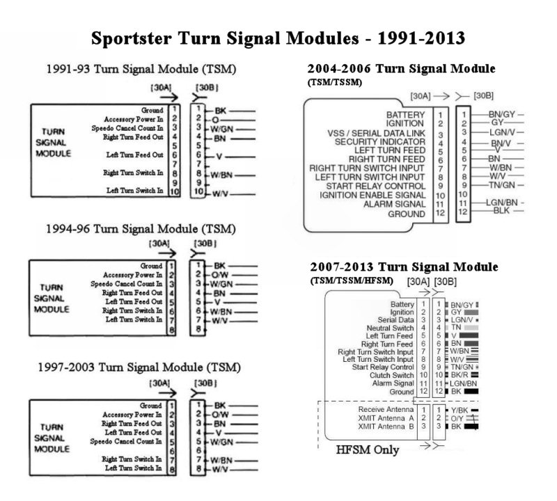
2014 - later BCM
(Body Control Module) —- The BCM (on 2014-later models) is used to supply power to most controlled circuits.
(Turn Signal Switch condition is input thru the CANbus.)
