Table of Contents
This is an old revision of the document!

IH: Engine Control
Factory Ignitions
Battery Ignition (circuit breaker/timer/distributor)
57-78 Sportsters (except XLC and XLCH)
- The ignition system has two circuits; (1)-the primary and (2)-the secondary circuits. 1)
- The primary circuit includes the battery, switch, primary coil and the breaker points.
- The secondary circuit consists of the secondary coil and the spark plugs.
- The breaker cam and contact points open and close the low tension circuit between the battery and the ignition coil.
(which causes the coil to produce high voltage discharge to the spark plugs) - The circuit breaker also times the discharge for proper engine firing.
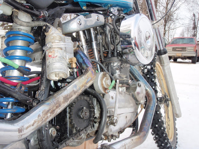
- The circuit breaker ignition was not factory installed on XLCH engines.
- However, they provide consistent lighting for riding at night.
- The magneto has been changed out to a circuit breaker ignition on many XLCHs
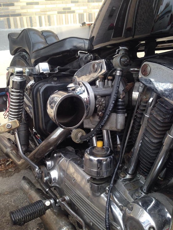
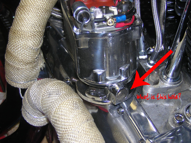
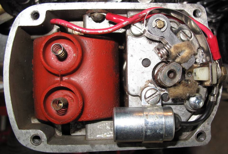
| Circuit breaker ignition on a 70 model XLCH 2) |
 |
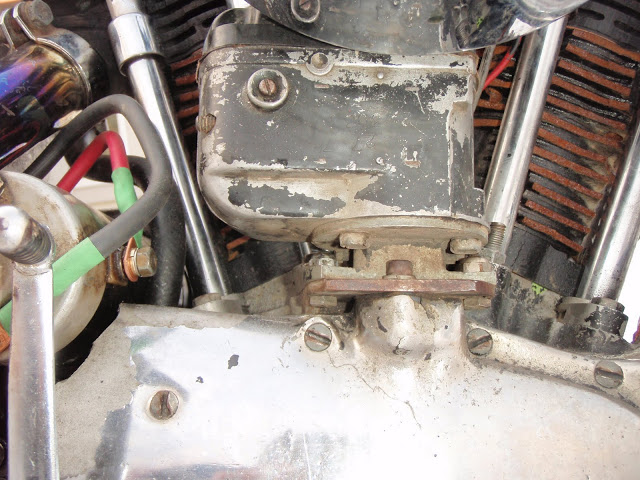
Single Contact Points - Manual Advance
A single contact point circuit breaker is operated by a cam with a narrow lobe and a wide lobe. 3)
- The narrow lobe times the front cylinder.
- The wide lobe times the rear cylinder.
- A single ignition coil fires both spark plugs at the same time.
- One cylinder on compression stroke, firing the combustion gas creating the power stroke.
- The other cylinder through the exhaust stroke.
- Timing is advanced or retarded by manually rotating the circuit breaker base in relation to the breaker cam.
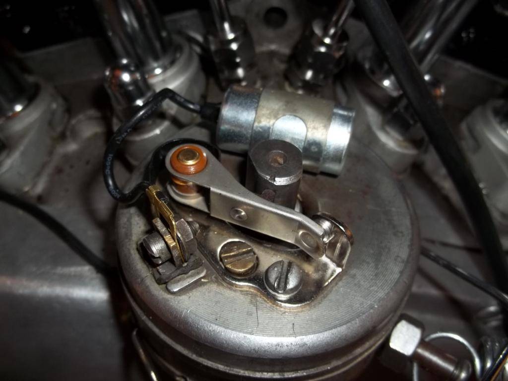 |  |
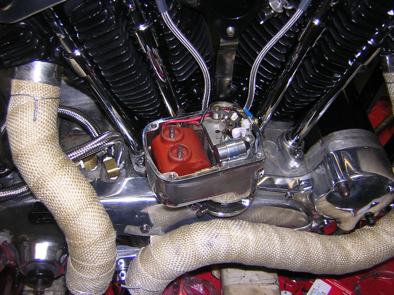
| Single Point Circuit Breaker on a 57 XL 4) | |
Single Contact Points - Auto Advance
The single set of points are operated the same way as the manual advance (by a cam with a narrow lobe and a wide lobe) with the addition flyweights.
(the spark timing cam is advanced automatically with engine speed) 5)
- The narrow lobe times the front cylinder.
- The wide lobe times the rear cylinder.
- A single ignition coil fires both spark plugs at the same time.
- One cylinder on compression stroke, firing the combustion gas creating the power stroke.
- The other cylinder through the exhaust stroke.
- Timing is advanced or retarded with an increase or decrease of engine speed by the action of the flyweights.
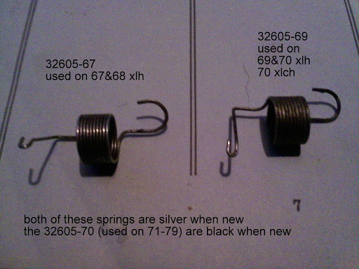
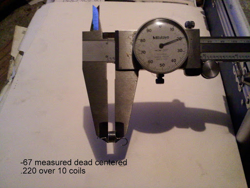
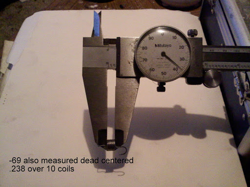
Auto Advance / Breaker Weight Springs
- Starting on January 3, 1969, the MoCo changed the size of the wire of the two ignition timer weight springs on Electra Glide and Sportster models to increase the speed at which timing advance occurred. This was to insure that the spark timing would be fully retarded at cranking speed and will advance gradually as RPMs increase to the fully advanced position. 6)
- Auto advance 1st appeared on the 1965 XLH. It was also used on the 1966 XLH also. 7)
- The black -70 springs in these timers don't seem to work nearly as good as when using either -67 or -69. 12)
| 1967-1968 XLH | 32605-67 using (0.022“ wire) - fully advanced at 1600 RPM 13) |
| 1969-1970 XLH 1970 XLCH | 32605-69 using (0.016” wire) - fully advanced at 900 RPM 14) |
| 1971-1979 XLH / XLCH | 32605-70 15) |
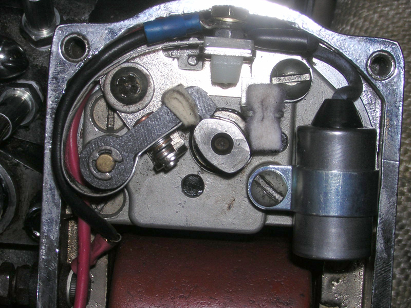
- Before checking ignition timing, remove the circuit breaker plate nuts and plate cover to make sure the flyweights will move freely. The cam must return back to retarded position when the engine is stopped. If it doesn't retard fully, it usually causes failure of the starter drive. 18)
- Also, on 1967 and later models, make sure that the bent end of the flyweight spring is hooked through the bottom hole and the upper loop grips the retaining groove in the pin tightly. 19)
- Replace the breaker plate cover and set the point gap at 0.020“ before checking / setting the advance timing. 20)
Dual Contact Points
Two independent sets of points are operated by separate cam lobes (each having it's own cam). 21)
- Each breaker cam opens the points individually which fires to the alternate cylinders with every revolution of the crankshaft
- Dual ignition coils (one for each spark plug) fire each cylinder independently.
- Timing is advanced or retarded by the breaking of each set of points by the single lobe cam on the timer shaft.
Circuit Breaker Cam
The circuit breaker cam, or ignition timer cam, (newly designed for the 1971 model year) was redesigned for the 1972 model year and was recommended as a replacement for parts order on 1971 model Sportster, Electra Glide and Super Glide models. The 1971 (32542-70) cam had a more rounder profile while the 1972 cam (32542-70A) was more radical with sharper corners at the sides with a flat or straight edge ascend to the cam top center from each side. The 1972 cam allowed greater range in point gap adjustment making (the adjustment less critical) and timing more consistent from cylinder to cylinder. Point gap specs remained the same between the two cams but the dwell changed from 90° to 140° with the '72 cam.
| Ignition Timer Cam | ||
| 1965-1970 | XLH | 32542-64A |
| 1970 | XLCH | 32542-64A |
| 1971 | XLH/XLCH | 32542-70 (original) |
| 1971-1978 | XLH/XLCH | 32542-70A (new design) |
Magneto Ignition System
(58-59 XLC and 58-69 XLCH) 22) 23)
The magneto produces a high voltage discharge to the spark plug which is timed to each cylinder's compression stroke.
It also eliminated the need for a battery for ignition. 24) as you can kick start or bump start the bike at about 2-1/2 MPH or less. 25)
- Components include a single induction coil, a rotating magnet (rotor), a condenser, a circuit breaker and a circuit breaker cam. 26)
- Ignition is timed when the front cylinder piston is 11/16” / (45° of crankshaft rotation) before TDC on the compression stroke.
Upon setting the proper timing adjustments at the factory;
Timing alignment marks were stamped on the drive housing plate and rear edges of the magneto adapter plate for future timing adjustments. 27) - A grounding circuit is connected to a button on the right handlebar (stop switch) that breaks the circuit to the ignition and stops the engine.
- Magneto mount changes:
- (1958-1964) Magneto is mounted in a fixed position producing advanced spark timing only.
- (1965-1968) Magneto is mounted on a movable plate allowing for spark timing retard.
Solid Mount Magneto
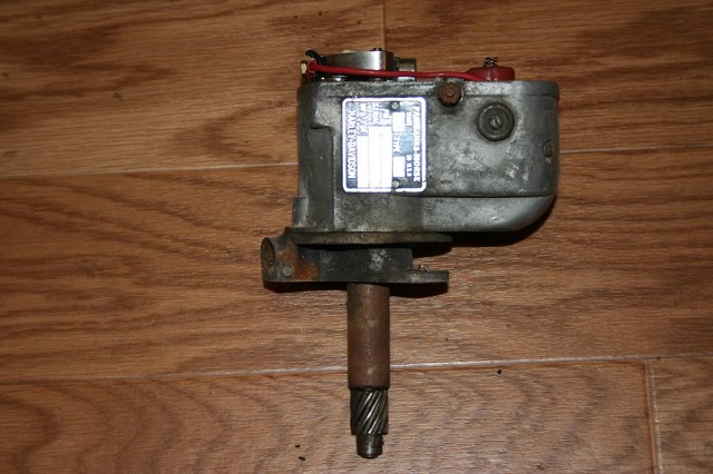
Adjustable Mount Magneto
AKA Retard Mag
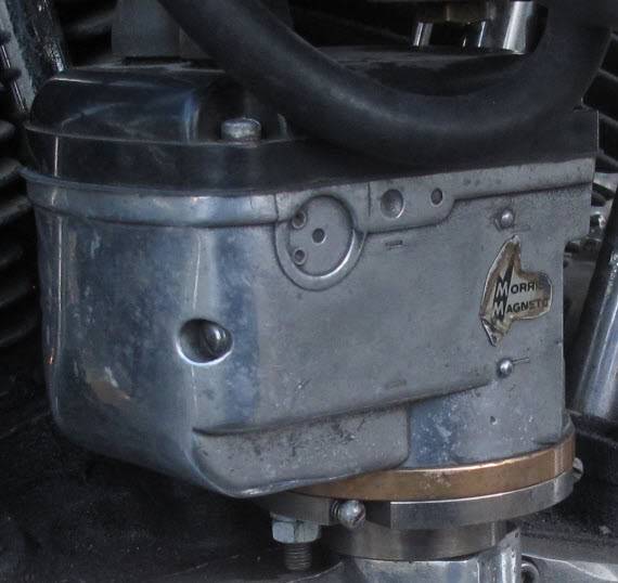
| Morris Magneto (MM3) 31) | |
 |  |
Prestolite Electronic Ignition System
(1979) Upgrade to the breaker point system in which the mechanical points are replaced by a breaker-less electronic ignition on the camshaft. Timer has a rotor with one small lobe and one large lobe and a sensor that sends signal to the control module on the back of the timer inner cover. Rotor is mounted on a mechanical flywheel centrifugal advance like a point cam would be in a breaker point system. The rotor's small lobe fires the front cylinder and the large lobe fires the rear cylinder. 32)1979 Ignition Module Assembly part number 32598-78 33).
- In November of 1978, the MoCo issued a few recommendations to dealers to handle issues with the leaned out condition related to this new ignition system. Motorcycles operate with leaner air/fuel mixtures and are more sensitive to carburetor mixture settings / ignition spark. 34)
- This involves checking the carburetor / manifold for leaks and insuring that the air cleaner backing plate has a tight connection. Corrective measures regarding the ignition on 1100, 1200 and 1340cc engines include: 35)
- Checking that the spark plugs, cables, boots and wiring connections are in good condition. If irregular running or spitting persists after making previously suggested checks, the spark plug gap should be increased to .060“. This has been found to improve engine combustion in some cases. 36)
- Make sure the ignition timer air gap is set as close as possible to the lower limit. Use a .004” feeler gauge to set clearance between the sensor and the trigger lobes per the FSM. Check both lobes to be sure they do not touch the sensor body. Review the FSM ignition section for other possible ignition system faults. 37)
- In May of 1980, the MoCo issued a Service Bulletin in response to having some owners of 1000cc and 1340cc engines, built since January 1, 1978, experience a knocking and / or pinging due to the unavailability of fuels with high enough octane ratings. Although retarding the spark advance will help to eliminate the knocking / pinging in an engine, a slight loss of power and fuel economy may be noticed by the owner. 38)
- However, reducing the spark advance on these engines a small amount, anywhere between 1°-10°, can help to eliminate this problem.
- Check the ignition timing to make sure it is set properly as described in the Service Manual.
- Set the timing if necessary:
- Turn the engine over until the timing mark is at the extreme front edge of the timing hole.
- Make a new timing mark with a piece of chalk at the extreme rear edge of the timing hole.
- Start the engine and set the idle speed at 2000 rpm. Retard the timing by shifting the timer plate so the new timing mark moves toward the front of the timing inspection hole. The timing advance should only be reduced in 2-1/2° increments and only enough to correct the problem. Timing should not be changed more than 10° (when the new timing mark is at the extreme front edge of the timing inspection hole).
Magnavox Electronic Ignition Systems
- (1980 to 2003) Components include a timing rotor (timing cup), sensor plate or inductive pickup, ignition control module, ignition coil and spark plugs. For electronic advance, the inductive pickup generates TDC pulses that are sent to the solid state Ignition Control Module (ICM). The ICM computes ignition timing advance and coil dwell. In 1983, a Vacuum-Operated Electric Switch (VOES) was added to switch between 2 different spark advance curves built into the ICM. 39)
- This uses a Dual-Fire Spark system, using only one coil trigger wire to produce a spark on both plugs at the same time. (See coil information)
- The spark advance start point can be altered by physically moving the sensor plate in the “nosecone”.
- In May of 1980, the MoCo issued a Service Bulletin in response to having some owners of 1000cc and 1340cc engines, built since January 1, 1978, experience a knocking and / or pinging due to the unavailability of fuels with high enough octane ratings. Although retarding the spark advance will help to eliminate the knocking / pinging in an engine, a slight loss of power and fuel economy may be noticed by the owner. 40)
- However, reducing the spark advance on these engines a small amount, anywhere between 1°-10°, can help to eliminate this problem.
- Check the ignition timing to make sure it is set properly as described in the Service Manual.
- Set the timing if necessary:
- Start the engine and set the idle speed at 2000 rpm.
- Retard the timing by shifting the timer plate counter clockwise in 2-1/2° increments until the problem is correct. Do not retard the timing more than 10°.
- In February of 1981, the MoCo issued a Service Bulletin regarding the time intervals for initial firing with the ignition module. 41)
- The electronic ignition modules have a protective control circuit that stops current flow to the ignition coil, if the engine is not running. This prevents overheating the ignition coil and limits the drain on the battery.
- 1980 and E1981 ignition modules, with the part number suffix -80 (Sportster part number 32410-80 42) ), have a 4 second delay and will only start firing on the second or third stroke. This causes a problem on kick-start motorcycles, where there may be a pause between kicks.
- Newer modules, with part number suffix -80A (Sportster part number 32410-80A 43) ), have a 6 second delay and will fire on the first compression stroke.
- Either module can be reset, if the protective circuit shuts off current flow, by turning the ignition switch or engine·stop switch off, then back on again.
- The new modules will work in 1980 and E1981 applications without modification.
VOES - Vacuum-Operated Electric Switch
- The computerized, microprocessor ignition module is programmed with two spark advance curves to meet varying engine loads. The system includes a vacuum operated electric switch (VOES). 44)
- The ignition module selects the proper curve when it receives an open or closed electrical signal from the VOES. This system ensures correct timing to suit starting, low speeds and highway speeds. 45)
- The VOES was first installed on Sportsters in 1983 (and used on most models thru 2013). The unit senses intake manifold vacuum through an opening in the carburetor body via a vacuum hose and requests from the Ignition Control Module switches between one of two different spark advance curves. The switch is closed at high vacuum operation (low engine load), utilizing a more advanced spark curve and it is open at low vacuum operation (high engine load), utilizing a less advanced (retarded) spark curve to minimize engine knock and still maintain performance. The VOES is installed above the intake manifold. 46)
- The high vacuum curve selected for maximum spark advance under normal light load conditions provides improved fuel economy and performance.
- The low vacuum curve (retarded spark) minimizes spark knock, while maintaining performance under high load conditions.
- VOES: Its Operation & Adjustment. (Article by IXL2Relax of the XLFORUM)47)
- There are many discussions on the XLForum and elsewhere regarding the VOES unit. While there are many helpful posts among those discussions, there is still much confusion due to posts that are inaccurate. I hope to clarify the VOES operation with this post and a reference diagram.
- The VOES unit was used on the Sportster from about 1983 (Ironhead) to 2003 (Evos). But, note that the 1998 to 2003 Sport models did not have a VOES but rather pioneered the use of a MAP sensor like that used on 2004 and later model Sportsters. Those models have Engine Control Modules which can micro-manage the ignition advance based on multiple conditions.
Here's what the VOES looks like with a quick reference chart of it's operation:
 48)
48)
- .
- What it does and how.
- The VOES works in conjuction with the ignition module to control ignition timing. The ignition module has two timing curves - one is for idling or cruising and the other is for WOT and/or for powering up for high loads (like steep hills). The VOES switches the ignition module between these two pre-programmed advance curves based on manifold vacuum.
- The VOES has two connections and one adjusting screw. The VOES is connected to the carb (manifold side) through a vacuum hose and monitors the manifold vacuum level. It is also connected to the ignition module. It has two black wires from the internal switch. From the inline connector, there is a (purple or purple/white) single wire sent to the ignition module and a second wire sent to ground. The VOES switching point is set by a concealed screw. This causes the ignition module to switch between the two advance curves based on a set point level of manifold vacuum.
- The adjusting screw is inside a sealed opening on the VOES. You must dig out the silicone sealing compound in order to make any adjustments. Remember - When testing your adjustments, you must also seal that opening with your thumb (or other air-tight sealing compound or tape) in order to prevent air leakage through the screw adjuster.
- The only function of the VOES is to switch between the two advance curves that are programed into the ignition module. Different ignition modules have different curves. Those curves have anywhere from 5 to 18 degrees difference in the advance settings between them. But that's another discussion.
- The manifold vacuum directly controls the VOES, but the throttle position (and/or it's aggressive changes) indirectly alters the VOES (thru changes in the manifold vacuum) by altering the carburetor throttle plate.
- When the engine is running at idle, when lightly accelerating or when using a steady cruise throttle, manifold vacuum is high (the throttle plate is mostly closed) and the VOES switch is ON, causing the ignition module to use the MORE ADVANCED CURVE.
- When the engine is not running or when the throttle is quickly opened to accelerate or to satisfy a heavy load (steep hill, extra weight, etc.), the manifold vacuum drops and the VOES switch goes OFF, causing the ignition module to use the RETARDED (OR LESS ADVANCED) CURVE. If you let off the throttle (when you reach your speed or top the hill), the manifold vacuum rises again. The VOES senses this and will again switch ON, causing the ignition module to return to the MORE ADVANCED CURVE as the load on the engine becomes lighter.
- Running without a VOES causes the ignition to run on ONLY the less-advanced power curve. The ignition module cannot switch curves. Unless you have a highly modified engine, this will hamper smooth engine operation on light acceleration and reduce fuel savings during cruising.
- Also note, if the VOES switching point is set too low, it will remain on the more advanced curve too long under mid-load acceleration and pinging will occur. This is the reason that engines with upgraded performance should have their VOES switch point increased (switch at a higher vacuum level) to better match the capabilities of the engine.
- Testing the VOES Operation
- Method #1 49)
- After the engine timing has been properly checked / adjusted, perform the following check:
- With the engine idling, remove the vacuum hose from the carburetor and momentarily plug the carburetor fitting. Timing will retard and engine speed should decrease. Reinstall the vacuum hose to the carburetor. The timing mark should reappear and engine speed should increase to the preset speed. If the engine speed does not decrease and increase as described, check the VOES wiring connection to the computer module and ground wire. VOES must be replaced if malfunctioning.
- Method #2 50)
- You will need a vacuum pump (with gauge) to create the desired vacuum level and an ohm meter.
- Remove the air cleaner, disconnect the switch wire from the computer module connector under the fuel tank and remove the switch vacuum hose from the carburetor. The rear of fuel tank may have to be raised to disconnect the switch lead connector from the computer module connector.
- Attach the ohmmeter leads to the switch wire and to ground. Attach the vacuum pump hose to the switch vacuum hose.
- The ohmmeter should indicate the switch closed with 3.5 to 4.5 in. of mercury vacuum applied. If more or less vacuum is required to close the switch, replace it.
- Testing the VOES Switch Point
- To test your VOES unit (or adjust it to a specific switching point), you will need a vacuum pump (with gauge) to create the desired vacuum level and an ohm meter to test whether the VOES has switched on (causing a short between it's wires).
- To work on the VOES, remove the vacuum hose from the vacuum line tee where it branches to the vacuum-operated petcock. If you don't have a vacuum-operated petcock, and have no tee, you need to remove the vacuum hose from the carb. Then remove the VOES from it's mount under the fuel tank and disconnect the wires.
- Connect your vacuum pump to the hose and connect your meter (set on ohms) to both wires. As you slowly pump up the vacuum, there will come a point where the meter will switch from infinity to zero ohms. This is the switch point. Write down the indicated vacuum (inches of mercury). Release the vacuum and do the test again, just to be sure you get a consistant reading.
- If the reading is right (according to the manual or chart above) for your bike, you can leave it as it is. If your bike is stock or only upgraded to Stage 1 level, you probably do not need to alter the factory VOES setting. But if you've gone farther with your mods, you might have one of those engine builds where the combination of ignition curves, cams, heads, etc., leaves you with some pinging near the VOES switch point. If you want to make your VOES switch at a different point, read on.
- Adjusting the VOES Switch Point
- Dig out the original sealing compound which fills the opening where the adjusting screw is located. Do this carefully so as not to damage the internal screw or diaphragm or the VOES housing. Remember - When testing your adjustments, you must also seal that opening with your thumb (or other air-tight sealing compound or tape) in order to prevent air leakage through the screw adjuster which will skew your readings.
- To adjust the VOES to switch at a higher vacuum, turn the adjuster screw 1/4 turn clockwise. Now repeat the test from above to see where (in inches of mercury) the new switch point occurs. If you want it to switch at a lower vacuum level, turn the adjuster screw 1/4 turn counter-clockwise. Keep adjusting the screw (carefully) to raise or lower the switch point. You should not go more than 1 or 2 full turns from the initial setting. If you turn the screw too far clockwise, you'll damage the internal diaphragm and need to replace the unit.
- When you are done making adjustments, you'll need to plug up that hole. But do this very carefully - Be sure you DON'T GET ANY SILICONE DOWN NEAR THE SCREW. Use only enough to plug the end of the opening and then set it aside to fully cure (probably 24 hours) before reinstalling on your bike.
- Variety of VOES
- From the book '101 HD Evo Performance Projects by Kip Woodring & Kenna Love', HD installed VOES on different models with their adjustment set for different switching points. These vacuum settings are measured in inches of mercury. The VOES are color-coded at the sealed end to indicate what setting was used on a particular unit. (I have seen very few with colors other than the natural greyish white - so perhaps HD did not keep up this practice)
- No Color - - - 7.0 in. Mercury – Early Evo FLT (1984)
- RED Color- - - 5.5 in. Mercury – Late Evo FLT
- WHITE Color - 4.0 in. Mercury – Evo FXR & XL
- BLUE Color - - 4.0 in. Mercury – Evo Softail
- All of these VOES should be adjustable to other settings. As far as I know, there is no difference in the various VOES units themselves other than their predefined factory settings.
- READER BEWARE!!! …NOT EVERYTHING YOU READ ONLINE IS VALID INFORMATION…
- There's a lot of MIS-information about the VOES & its operation!
- There are many threads with references to the VOES and how it works, or how it should be adjusted, or what effect it will have. I've only posted above some of the information that is valid. But there is so much confusion surrounding the VOES that you must read all statements carefully to keep from being misled.
- There is a Sticky Thread in the 'Engine Conversion' section titled 'VOES ADJUSTMENT' - Be careful of the information presented there regarding the VOES. “This is the most confusing conglomeration of instructions I have ever read. There is some bad info, some completely wrong info, and some very dangerous info.” (A comment from Post# 113)
- That thread has some information about connecting an LED light to the VOES-to-Ignition wire to see the VOES switching modes while riding. If you try this, just be careful to read the information thoroughly and understand what you're doing before proceeding. This is the link to that thread: http://xlforum.net/forums/s...ad.php?t=57534
- For the sake of not repeating what can be looked up directly, the following links have VOES discussions (as well as other info).
- Additional References:
- http://xlforum.net/forums/s...d.php?t=594019 - Thread not all VOES related
- These posts from the above thread are most applicable:
- This post has some great pictures of the inside of the VOES:
Coil
Sub-Documents
* . . . Coil Mix-up on 1973-1974 Models
* . . . Failed Coils on 1980 Models
Spark Plugs
| Year Model | Use/Type HD Plug | Alt. Plug Brand/Number | Ignition Type Spark Gap | |
|---|---|---|---|---|
| 1959-196952) | Avg-HD 4, Hard-HD 5 | .. | Magneto Ign. 0.020 in. | Battery Ign 0.025-0.030 in. |
| 1970-197853) | Avg-HD 4, Hard-HD 5 | .. | Magneto or Battery Ign. 0.025-0.030 in. | |
| 197954)55) | HD 4, 4R56) radio static suppression), 4R5 (resistor type) | .. | Breakerless Ign.0.060“ (No 4 plug- 0.040 in.) | |
| 1980-198557) | HD 4, 5, 4R5 (resistor type) | Autolite 4123 Bosch W5AC Champion RL82YC NGK B6HS Screamin Eagle 2413 | Electronic Ign. 0.038-0.043” | |
Timing
Sub-Documents
Timing and Ignition Components
Clean the timing mark on the flywheel and apply a paint color that will stand out when viewing it with a timing light. 58)
You can spray some brake cleaner on a Q-tip to clean the timing mark.
Paint the timing mark with bright pink fingernail polish (or something florescent).
Install the clear plug into the timing hole.
It should be very near but not touching the flywheel. (go in till you touch the wheel and back off a 1/8-1/4 turn).
- During the 1969 model year, the MoCo began a new practice of setting ignition timing on Electra Glide, Servicar and Sportster models with the circuit breaker cam fully advanced instead of in the retarded position done in the past. Correct timing position was changed to 45° BTDC on Sportsters. Good engine performance requires correct advanced timing and this procedure eliminates any variations which may happen , in degrees of timing, due to a tolerance buildup in the parts. Retarded cam timing is not as critical since it is effective only at low speeds. 59)
- When checking / setting timing with a circuit tester or timing light (according to the FSM), ignition should occur when the single mark on the flywheel is in the center of the timing inspection hole in the crankcase. 60)
- Checking / Setting timing on 1983 → models. 63)
- When checking timing advance, always check the VOES operation See Testing the VOES Operation. Failure to do so may result in running engine with too much spark advance which could lead to extreme engine knock and / or engine failure.
- Ignition timing should be checked every 2500 miles.
- Use an Inductive Timing Light to view the advanced timing of the flywheel through the accessory plastic view plug (HD-96295-65) screwed into the timing inspection hole. Make sure the view plug does not touch the flywheels. Timing light leads should be connected to the front spark plug cable, ground and battery positive terminal. Make sure the vacuum hose is properly installed at the carburetor and at the VOES. Start the engine and set the engine speed at 1300 rpm. Light will flash each time spark occurs. Loosen the sensor plate screws just enough so that plate can be shifted using a screwdriver in the notch as the light (aimed into the inspection hole) stops the timing mark in the center of the hole.
| 1000cc 4 Speed Timing Range | |
| Range | 10°-55° |
| Start | 10° |
| Fast Idle | 40° |
| 1800-2800 RPM | 55° |
Ignition Lubrication
- Only a small amount of Hi-Temp grease is recommended for proper lubrication of the cam surface, camshaft, advance weight pins and underneath the advance weights. Too much grease may melt away during service (Over lubrication can cause grease to migrate between the point contacts causing burning). See your FSM for proper assembly guidelines.
- Ignition advance lubrication change in 1976: Due to normal engine combustion and friction, high temps may be present in the timer compartment and timer components. These high temps could partially dehydrate the installed grease and cause stiffening or gumminess, especially at the pivot pins and timer shaft. Normal operation keeps the assembly free but timer adjustments are more difficult. Since August, on all production engines, the timer weight assemblies and breaker cam posts have been sprayed with “Never-Seez”, a spray can type lubricant when making timer adjustments. Never Seez or Locktite Anit-Sieze was suggested for dealer use along with a high temp grease on the point cam rubbing block. 64)