Table of Contents
IH: Engine Mechanicals - Sub-02C
Installing, Pinning and Reaming Cam Bushings
See also in the Sportsterpedia:
Selecting Bushings
The factory machine work on 70< cam covers is stellar. 1)
Reproducing it at home is nearly impossible. Even in a full machine shop its very time consuming.
A good (at home) job is possible if you know what your doing.
- To begin a solid bush job you need a solid cover.
It's the fine fit, finish, size, and position the factory did on the cover bores that allow you to do a home repair. - Be careful not to muck up the cover bores.
If you're using a claw puller, make sure the claws wont drag on cover bores during removal.
If running a tap in old bushes and using the threads to pull on, make sure the tap goes in straight.
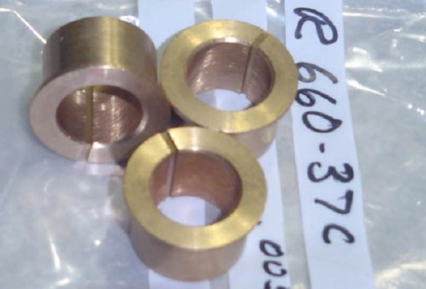
Scope out the new bushes. It's the quality of the pre-installed bushes that govern much of the final result. - Selecting replacement bushings:
- O.D.: Small bushes nominal +.002“ with a +/- .0005” manufacturing tolerance.
Except a #1 bush should measure .9375 + .002“ +/- .0005”, so .939“ / .940”. A little bigger is ok, smaller isn't. - I.D.: Should be at nominal before install. Slip them over the cams. Does the flange contact the cam face? If not find out why.
Maybe the lead-in chamfer is too small, fouling on the shaft radius. - Concentricity: .001“ max. Hold the cam in a vice. Slip bushing over cam and put indicator on the press fit area of bushing.
Spin the bushing with a .001” max variance on the indicator. - Length: The press fit area needs to be shorter than the bore depth in cover.
- Flange Thickness: .060“ / .065”.
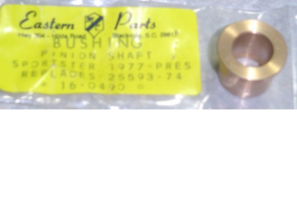
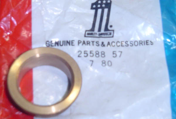
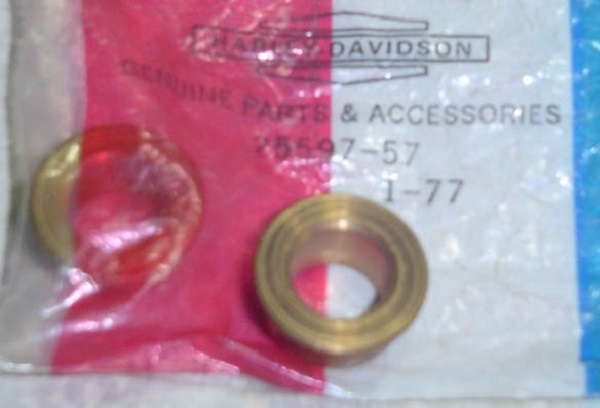
- Pinion shaft bushings
- 1952-1976 bushing (25593-57) uses a .625“ pinion bushing bore. 2)
- 1977-2020 bushing (25593-74) uses a .562” pinion bushing bore.
Removing Bushings
Bushings that haven't already spun out will need to be pulled out.
See also Cam Bushing Measuring / Removal / Installation Tools in the Sportsterpedia for some ideas on tools you can use to remove the bushings.
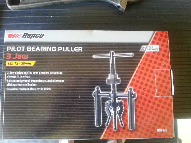
| Check local auto parts stores for a pilot bearing puller. 3) |
 |
Installing Bushings
- Bearing bronze into aluminum at room temp is a good matchup. There are no material shaving or galling problems associated with it. 4)
- Just make sure there are no sharp edges on the bushing or cover bore.
You don't need to heat the case or freeze the bushing (unless you choose to).
The interference fit isn't great. One or both of the materials will flex under the interference. That adds up to the driving force never getting too great.
A note about heating aluminum; as temps rise, so does it's affinity for galling.
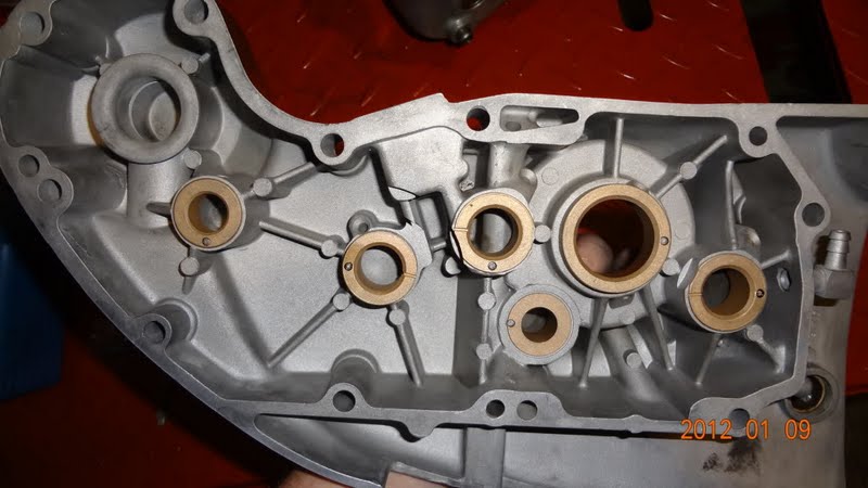
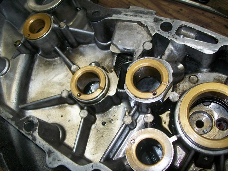
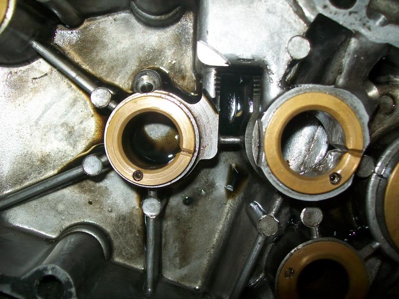
- Bushing groove placement:
- Compare the placement of the grooves in the bushings in the 68 and 78 cam covers below. It's the same.
Every factory cover is like this. So is the pin placement. - You have to look at the oiling. 5)
- You don't want a slotted bushing on the pinion shaft, because that is what feeds oil to the crank.
The slot would allow oil to run from the cover into the gearcase, bypassing the pinion shaft hole and starve the crank. - The intake with the big bushing gets an oil feed hole drilled in it. No need for the slot.
- The slots go at 9 or 3 O'clock on the other 4 (respectively).
- Grind the flanges from the bushings as required.
- With a die grinder, relieve the #1 & #3 flanges for gear tooth clearance. Grind until you match up with the cutouts in the cover.
- Using general hand tools: 6)
- You can put the bushings in the freezer for a few hours to shrink them some.
Then gently tap them in with an extension inserted the wrong way through a socket (smaller than the bushing flange).
It may not be the preferred method, but for someone with next to no tools, it does the trick.
- Using a hammer and driver:
- Driving bushes and bearings fitted within accepted moderate interferences (as HD has designed most to be) isn't an over the top operation.
A hammer and an annealed aluminum driver at room temps with some kind of lube works good.
Just go slow, observe and deduce, while applying your wrench sense and you will be fine.
- Drill the oil hole in the number #2 cam bushing.
- Use a bit same size as the hole in the cover. Drill thru the cover hole into bushing.
Now stop and look at the oil hole in cover now. It's been oblonged.
By the angled (in this case) drill walking off the bronze and being restrained by the aluminum.
- Ream the bushings. (see Reaming Bushings below)
- When the press fit squeezes the bushing, the I.D. will close somewhat. This collapse will be greater on the inner end of the bores.
Any interference fit will lead to some kind of distortion. Remember that last sentence when you get to pinning the bushings.
Click on a pic to enlarge.

Pining Bushings with Solid Pins
The factory uses pins because they cost less to make and install. Their install procedure is tuned to the tight tolerances pinning requires. 13)
- The pins are insurance. On a well done bush job, they don't do anything. What they are there for is to keep a bush that has worked loose in the cover from rotating. 14)
- What the factory did: Holes are .1215“ / .1220”. Pins are .1222“ / 1224”. The holes are drilled and then reamed.
- Now the FSM says to drill and install the pins. It never works out as well as the factory job.
Try to drill a hole in any material and hold .0005“. It's impossible to do at home.
It's extremely difficult in a full machine shop and even then, it's hit and miss. That's in one contiguous piece of material.
Try drilling a hole that's half in bronze and half in aluminum. Now it truly is impossible. - Ok, so what happens if your drilling goes sour?
- If your pins end up loose and your fits and alignments are cool, nothing happens.
As long as you peen the top of the pin hole so the pin can't walk into the rotating cam. - If your hole walks off the bronze and into the aluminum, and it will, that depends an how the pin fits in that hole.
- If the hole is banana shaped to the extent that the straight pin gets tight at it's extreme ends, you get a modified press fit.
- When ever the pins get pressed in, they distort the bushing bore.
No problem you say. The reamer will take care of that. And it does, sort of.
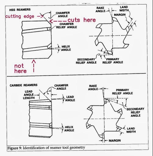
Here's the rub. A reamer cuts along its chamfer angle, not on it's outside diameter.
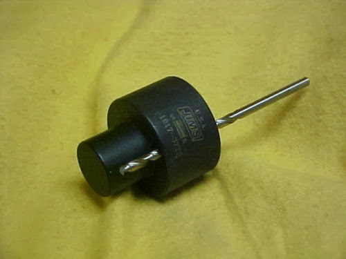
You can buy a drilling guide / jig to put the pin hole in the right place. They're a cheap investment.
If you have access to a machine shop, it would be a simple guide to make.
| Bushing Pining Jig 15) |
 |
Pining Bushings with a Set Screw
- Instead of using only 1 set screw per bushing, 2 set screws in same hole works better.
(one on top of the other, top one locked down on the bottom one).- You can use 2 set screws (#6-32 x 3/16” long) in each hole.
#6 is .138“ O.D. (slightly bigger than the pins)
#8 is .164” (a bit on the large side for the die cast cover, cool on the pre-AMF cover though).
- Now, what if your solid pins are too tight for any reason?
Your pre-reamed bushing hole is now egg-shaped due to press fit distortions.
This also moves the beginning reamer cut position around, off concentric if you will.
So the results of the pin job effects the final position of the bushing bore. - Whats a guy to do at home? Forget the pins, drill and tap for 1/4“ long #6-32 set screws instead.
This is way more user friendly. But it still needs special consideration due to the hole being half alum & half bronze. - What you need:
- 3/32” pilot drill (drill 3/8“ deep).
- Chase the hole with a #36 (.106” dia.). Once you hit the bottom of the pilot hole, stop drilling.
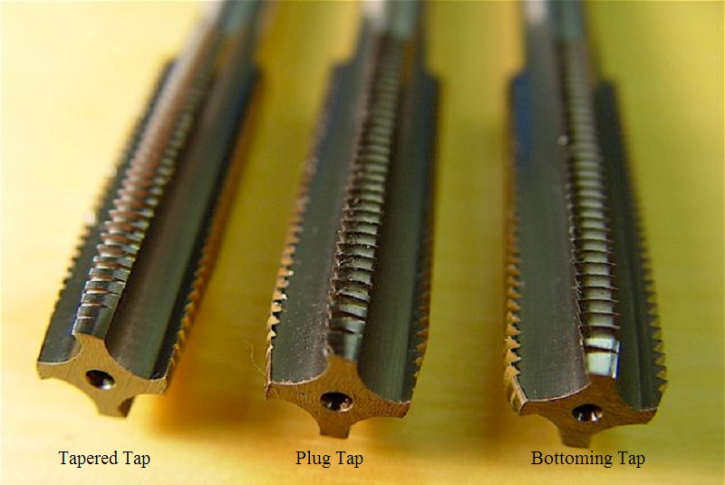
- Use a good professional quality high speed steel (HSS), plug chamfer, hand tap. See Types of Taps in the Sportsterpedia.
(no hardware store junk - go to your local industrial supply house). It needs to be a good tap if you expect it to deal with the bi-metal hole.
Don't get the 'spiral point' taps. Difference being the angled gash behind the 1st cutting threads.
Hand taps lack that gash angle. Suffice to say that the hand tap wont 'tap crooked' as easily as a spiral point will.
Now if the guy at the counter asks “what H limit you want”, tell him “the smallest he has but nothing bigger than H3”.
This tap will be marked with HS to denote its made from high speed steel and it will also have the H limit on it.
All good taps will have those two markings. - Also get a tee handle tap wrench. The centered tee makes for much less tap flexure when tapping.
It's flexing taps that break. Be it from misaligned wrench forces or too much twisting flex from high cutting forces.
HSS taps are much harder than their hardware store cousins. So they are less tolerant of flex.
- Doing the work.
- In order to avoid broken taps:
- Drills and taps from the supply house aren't very expensive.
If you double up and practice the whole operation on some scrap, you will have a much more secure feeling on what your doing when you get to your cam cover.
- Locate the holes to be tapped in the beefiest cover material area. 16)
- Your cutting tools need to be very sharp or you will have problems. Even slightly dull drills and taps will tend to bite into the aluminum and skid off the bronze.
- Drill and tap dry (oil makes this phenomenon of 'walking' worse) making your holes crooked and crappy.
- Drill .015“ / .030” smaller 1st as a pilot hole. Then chase to size with a finish drill. A drill press makes drilling less artsy fartsy.
- Once the hole is drilled and tapped install set screws. If need be, you shorten the leading end of screw.
Then GENTLY peen the top of hole so they can't unscrew into the rotating cams. You may need to remove the screws in the future.
Reaming Bushings
Reaming a hole is no more than a hole sizing operation. If the drilled hole is not on location and square the reamed hole will not be either. 19)
Boring the hole with a milling machine is the best option if possible.
For those guys who want the best job they can get, don't ream at all. Make your own bushes and in-position bore them in a mill just like the factory does. 20)
- The reamer wants to 'walk off' instead of cutting. It will only cut if the walk is resisted. What resists the walk?
- The fact that, at a point 180º around, the reamer is also doing the same thing.
- The forces are the same but in opposite directions so they cancel out and your reamer begins to cut.
And the position of the center of reamer is the center of the work hole. - Once the reamer is cutting, it's the O.D. of the reamer being held by the newly reamed I.D. that it has just created.
- So, what happens if the I.D. of the pre-reamed bushing is out of position (like if your bushes are not concentric)?
Your position goes to Hell, that's what. - Reamer sizes:
See also Calculating Pre-Ream Drill Hole Sizes (includes a pre-ream drill hole size chart) in the Sportsterpedia.
The reamer size and the holes they are supposed to produce is nominal. 21)- 9/16“ (.5625) for idler.
- 5/8” (.6250) for pinion.
- 11/16“ (.6875) for #1, #3, #4.
- 1-1/8” (1.1250) for #2.
- If reaming by hand, you'll need a guide sleeve to keep the reamer straight.
- It should be about .001“ / .002” larger than the shank of reamer that's gonna pass thru it.
(so the reamer isn't guided like its a fork tube with the sleeve being the lower leg)
Rather, it's like an axle that has passed thru one wheel bearing.
Until it gets into the 2nd bearing there is no solid alignment.
The second bearing in this case is the center of the bush bore.
- None of the #2 bushing options are gonna be cheap ($123 for a carbide tipped stub reamer)
That is cheap for solving this problem, if it does in fact solve it.
But there probably aren't many who agree that $123 is a cheap way out.
| A reamer cuts along its chamfer angle, not on its outside diameter. 22) | Bridge and Hand Reamers have a starting taper that is too long for blind hole work. Each has a different starting taper angle. 23) |
 | 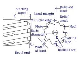 |
