Table of Contents
This is an old revision of the document!

IH: Oiling & Lubrication
Changing / Draining Engine Oil
Engine Oil Cycle (1976 and Earlier)
- Oil is gravity fed to the gear type oil pump. 1)
- A check valve in the oil pump prevents the oil from draining into the engine by gravity.2)
- Oil is forced from the feed side of the oil pump through the pinion gear shaft to lubricate the lower connecting rod bearings which splash oil to the cylinder walls, piston pin and main bearings.3)
- Oil is forced through the oil lines to lubricate the rocker arm bearings and rods, valve stems, valve springs and pushrod sockets, draining from heads through passages in each cylinder, then flowing into two holes in the base of each cylinder while lubricating the cylinder walls, piston, piston rings and main bearings.4)
- Oil flows from the rocker boxes into the gearcase compartment lubricating pushrods, tappets, tappet guides and tappet rollers.5)
- Oil accumulated in the crankcase is scavenged by the flywheels to the breather oil trap. The rotary breather valve is timed to open on the downward stroke of the pistons. This allows crankcase exhaust air pressure to expel scavenge oil from the crankcase breather oil trap into the timing gearcase. The breather valve closes on upward stroke of the pistons, creating vacuum in the crankcase.6)
- Oil blown and drained into the timing crankcase lubricates the generator drive gear, timing gears and gear shaft bearings.7)
- Gearcase oil flows through the fine mesh oil strainer preventing foreign particles from entering the scavenge section of the oil pump.10)
- Engine oil returns to the oil tank by the scavenge side of the oil pump and also supplies oil to the rear chain oiler 11)
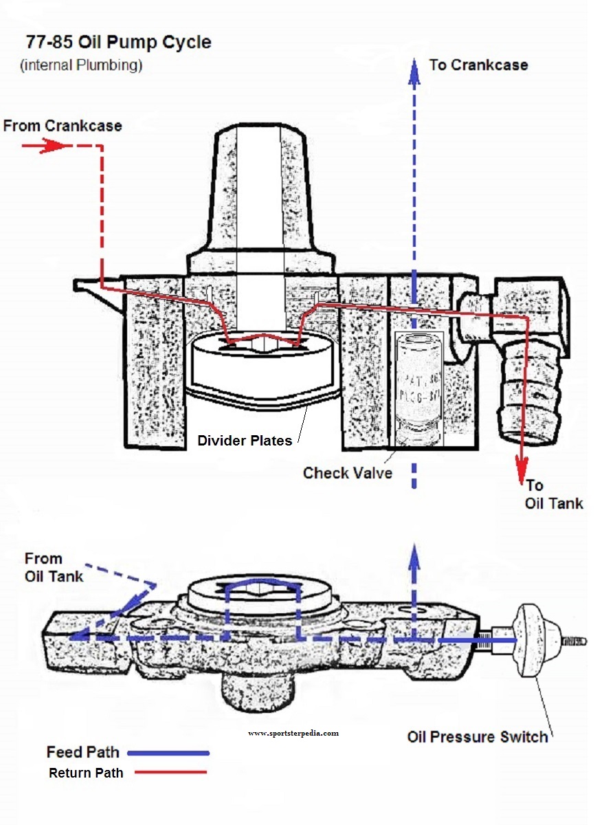
Engine Oil Cycle (1977 to 1985)
- Oil is gravity fed to the gerotor type oil pump. Oil enters the feed section and fills a cavity under the feed pump. Oil is transferred from the inlet cavity to a one way check valve located in the outlet line. 12)
- The check valve prevents gravity oil drainage from the oil tank to the engine and acts as a restriction to activate the pressure switch. The check valve is set to open between 4 psi and 6 psi of oil pressure. 13)
- As the oil pump pressurizes, it causes the oil pressure indicator light, sending unit to activate and the check valve opens. With the check valve open, oil flows into the right case half through a hole located in the oil pump gasket surface and into the gearcase cover passage through a hole in the gearcase cover gasket. 14)
- Oil is routed to the crankshaft and to the head areas. Oil enters a hole in the pinion gear shaft and travels to the right flywheel then through the flywheel to the crank pin. Oil is forced out of the crank pin through 3 holes located to properly lubricate the rod bearing assembly. 15)
- Oil that bypasses the pinion gear shaft travels upward through the gearcase cover to the right crankcase and through a channel in the crankcase to the overhead lines to both front and rear intake rocker arm shafts, lubricating the rocker arm shafts, bushings, intake valves and pushrods. 16)
- Oil continues around a groove machined in the outside diameter of the large end of the rocker arm shaft and through the rocker arm arm cover to the exhaust rocker arm shaft lubricating the rocker arm bushings, valves and pushrods in the same manner as is described for the intake shafts. 17)
- Oil collected in the pushrod area of the heads flows down the pushrod covers to lubricate the lifters. The lifter's rollers are lubricated by oil draining into the gearcase through the 2 drain holes in the lifter bodies. 18)
- Oil collected in the valve spring pockets drains to the flywheel compartment through horizontal holes in the cylinders. Oil returning from the heads, rod assembly and gearcase collects in the sump area below the flywheels. 19)
- Oil collected in the sump area returns to the scavenger section of the oil pump through a passage located in the rear section of the pump. Oil flow to the pump is accomplished by the scavenger effect of the oil pump and the pressure created from the downward stroke of the pistons. 20)
- Return oil fills a cavity above the scavenger section of the pump which transfers return oil to the outlet side of the pump and sends the oil back to the oil tank.
- All engine breathing is accomplished through the gearcase into the breather system. Any oil still carried by the exhaust air is centrifugally separated from the air by an oil slinger on the end of the generator drive gear shaft.21)
- Crankcase exhaust air is routed through a one way check valve to the air cleaner. 22)
Engine Oil Pressure (57-85)
See also Sportster Oil Pressure (57 to Present) in the REF section of the Sportsterpedia.
The oil pump is non-regulatory and delivers its entire volume of oil under pressure to the oil filter mount.
When an engine is cold, the engine oil will be more viscous (ie., thicker).
During start-up of a cold engine, oil pressure will be higher than normal and oil circulation will be somewhat restricted within the oiling system.
As the engine wams to normal operating temperature, the engine oil will warm up also and become less viscous - oil pressure will decrease.
When an engine is operated at high speeds;
The volume of oil circulated through the oiling system increases, resulting in higher oil pressure.
As engine speed is reduced, the volume of oil pumped is also reduced, resulting in lower oil pressure.
Engine oil pressure was measured (by the MoCo) with a pressure gauge at the oil pump.
Expected oil pump pressure per FSM's:
Gauge mounted at oil pump:
As checked with hot oil and a gauge at the oil pressure switch location at the oil pump.
The oil pressure switch has to be removed for the gauge to be installed.
1957-1969: 23)
Minimum: 3-7 psi (idle, with spark retarded)
Normal riding conditions: 10-14 psi (6 psi at 20 mph)
1970-1978: 24)
Minimum: 3-7 psi (idle)
Maximum: 15 psi (60 mph in high gear)
Normal riding conditions: 4-15 psi
1979-1985: 25)
Minimum: 4-7 psi (idle)
Maximum: 10-20 psi (3500 rpm)
Normal riding conditions: 4-15 psi
77-85
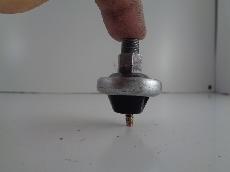
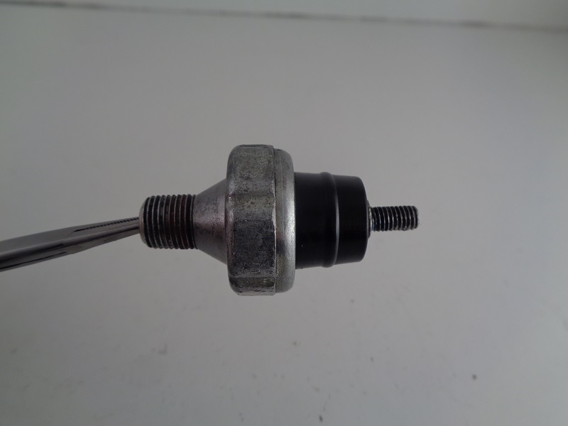
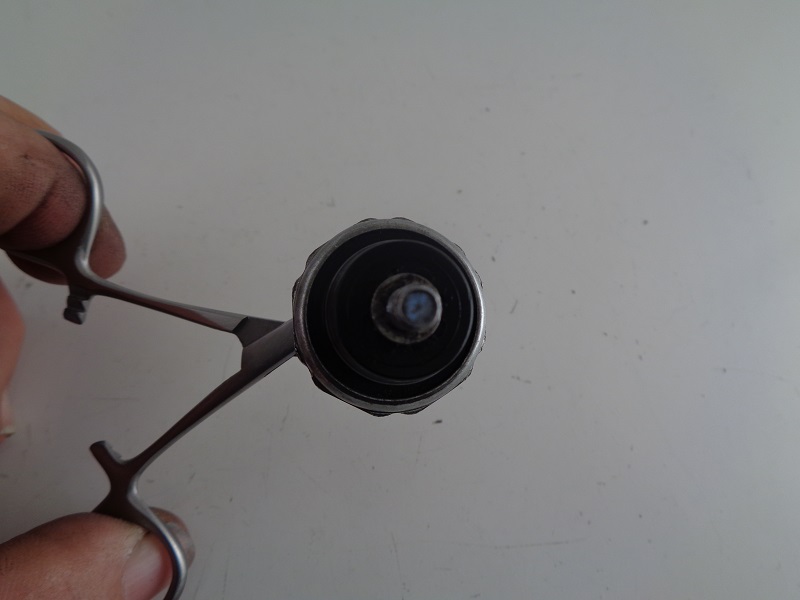
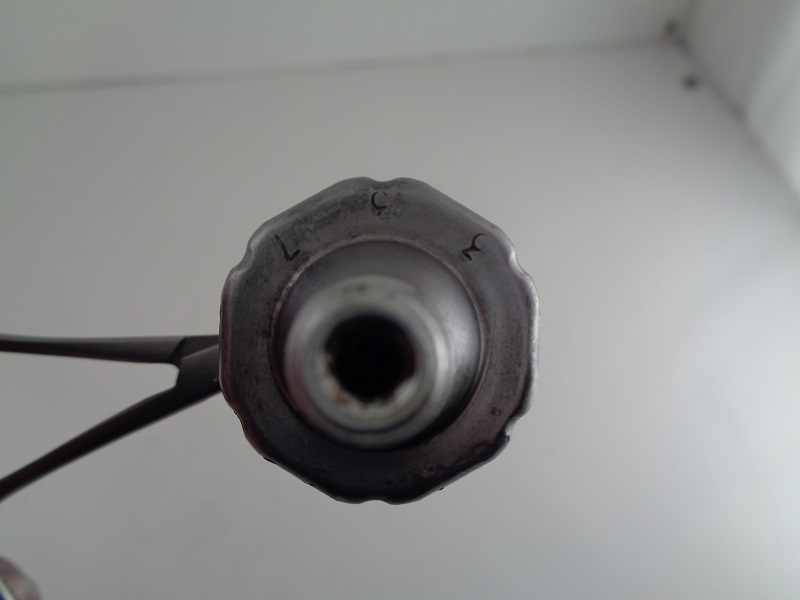
Oil Pressure Switch
The oil pressure switch (for the oil light) is a pressure actuated diaphragm type on / off switch basically.
The diaphragm is spring loaded and held against its contact point when then engine is not running or the when the oil pressure is too low while running.
With the switch contacts touching, this closes the circuit to the oil pressure light and causes it to light up (with the key on, of course).
When the engine is fired up, oil pressure builds in the oil pump, activates the oil light switch and opens the oil pump check valve (allowing oil to enter the engine)
Oil pressure is sensed by the oil pressure switch.
By the time the engine reaches over 1000 to 1200 rpms, the oil pressure is sufficient to move the oil pressure switch diaphragm completely off it's seat.
This opens its contact point, breaking the circuit to the oil pressure light and it goes off.
Cold cranking oil pressure can reach between 30 PSI and upwards of 60 PSI.
The 70-78 and 79-85 FSMs say oil pressure will vary from 4-15 PSI under normal riding conditions.
However, idle oil pressure will vary from 4-7 PSI (3-7 in the 70-78 FSM).
So, at idle, the oil pump check valve is barely opened past it's cracking pressure (not to it's end of travel).
In the Case of a Defective Oil Pump Switch:
This switch opens and closes the contacts to the oil pressure light.
The oil light is important to have since if it is not working, it can be assumed that you have little to none oil flow to the engine.
If the pressure switch doesn't operate the light it should be checked for proper operation or replaced.
For the $30 or whatever you save by not buying the switch, it's just not worth it to not have the low engine pressure idiot light working. 26)
If your motor is ready to run and you need to test it then you can connect a piece of clear hose so you can see oil in it.
Don't plug the end till you've primed the pump (with ignition off kick it over a few times until oil comes out the clear pipe where the pressure switch lives).
Replace a defective switch as soon as possible.
See also Testing the Oil Pressure Switch in the Sportsterpedia.
Oil Pressure Switch Pics
 |  |  |
 |  |  |
 |  |  |
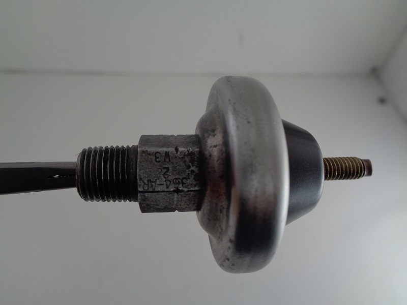
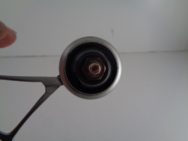
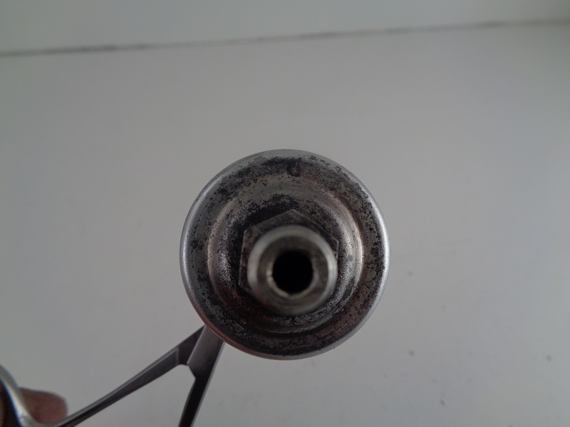
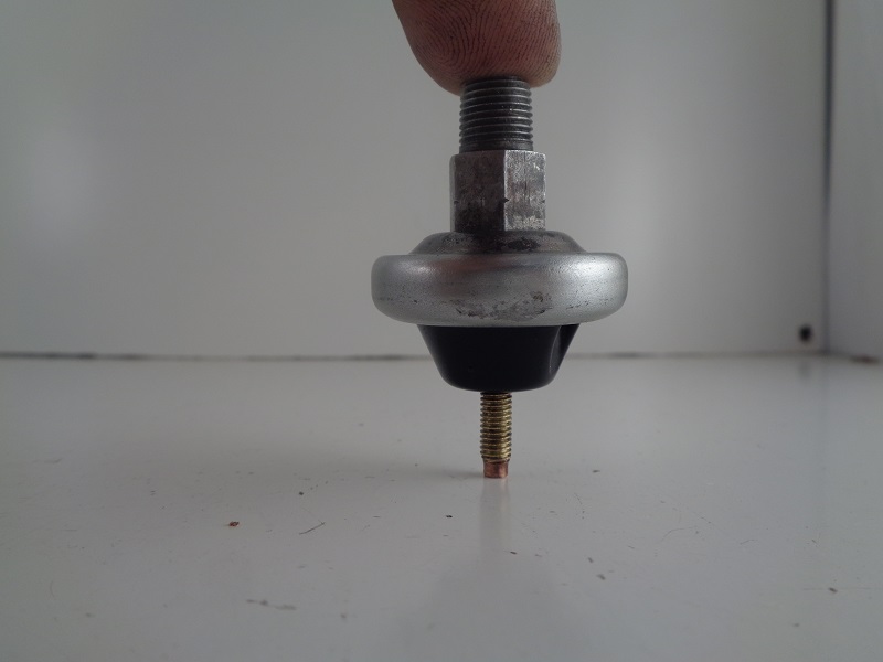
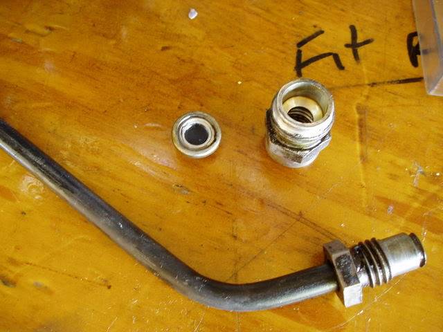
Oil Pump Check Valve
The oil pump check valve plays a role in the operation of the oil pressure switch.
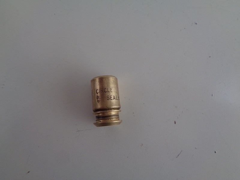
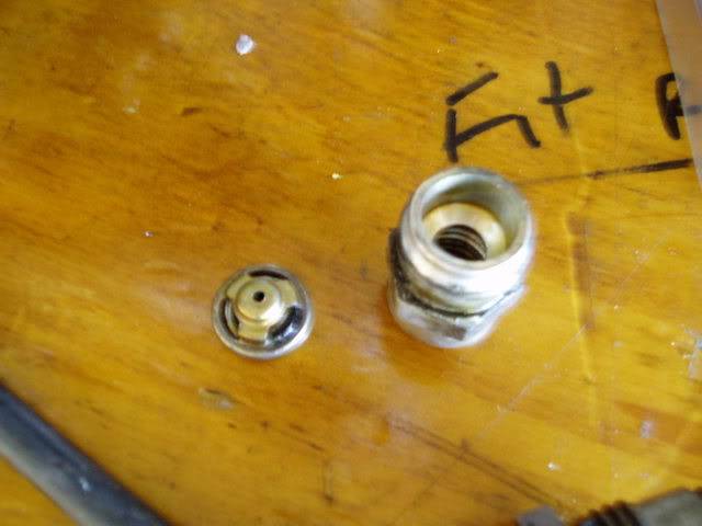
The check valve is not a pass through but instead a cartridge type one way check valve operated by a spring loaded cup against a seat pressing at 4-6 PSI.
Oil pressure enters the center of the check valve, lifts the cup against its spring and exits the check valve by pushing around and past the cup and into the engine.
At a point, the cup will float off it's seat up against the spring towards the end of it's travel.
According to the FSM, the check valve has two main functions;
It prevents gravity oil drainage from the tank to the engine when not in operation.
It also acts as a restriction to activate the oil pressure switch.
Without the check valve, the pressure would not build up as much in the pump.
It would free flow into the crankcase and disperse.
With the check valve installed and the oil having to find it's way around the cup, pressure builds behind it.
This back pressure builds inside the pump and pushes the pressure switch contacts open, shutting off the oil light.
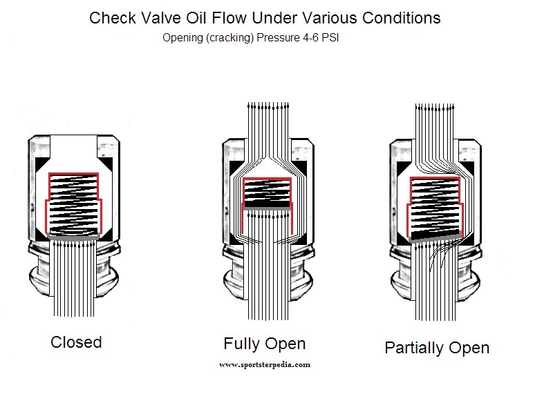
The cup will stay off it's seat and open as long as there is sufficient oil pressure pushing against its spring.
This spring actuates the 4-6 PSI pressure that the pump must overcome.
If there is not enough oil pressure coming from the pump to keep the check valve cup completely or partially off it's seat;
The back pressure from the spring will push the cup toward it's seat, or closed position, equal to the amount of minimum pressure loss from the pump.
Until the seat is fully closed, the remaining oil pressure will still try to push past the cup.
At a point, the pressure from the pump will not be sufficient to completely float the cup off it's seat.
So, the cup will turn sideways a bit only allowing oil to pass it on one side.
This reduction in pressure is also sensed by the oil pressure switch.
When the pressure drops, the diaphragm eases back toward the closed position.
If the pressure is low enough, the contacts will close or partially make contact while closing or intermittently opening and closing.
The oil light will come on or flicker depending on the action of the contacts.
The pressure switch requires no back pressure from the engine to stay open.
It opens solely from the pressure generated from the oil pump with the assistance of the check valve to hold some of that pressure in the pump.
So, it is possible but not likely to have a stuck closed check valve with no oil light on.
Oil Pressure Gauge
According to the MoCo (FSMs), the oil pump is the prime testing point of oil pressure to the engine.
The procedure is to take the oil pressure gauge off and install an oil gauge there.
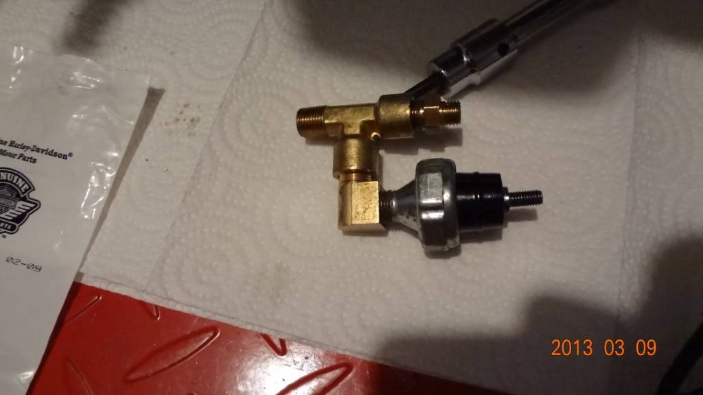
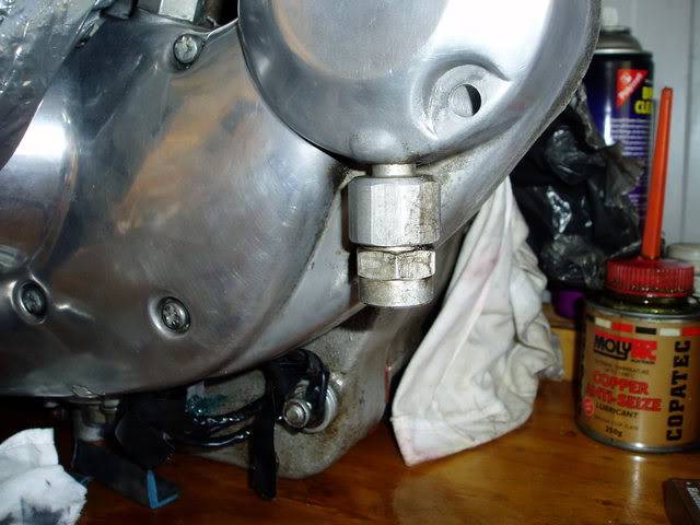
However, as in the pics below, a tee can be added inline for a dedicated gauge.
You can either mount a permanent gauge to the tap or plug it off until needed.
| Piping added to include the gauge and the oil pressure switch 27) | |
 |  |
Crankcase Ventilation
(or Foo Foo Valve)
Ironhead Engine breather 101 Through 1985
WHAT IS IT?
- The slang term “FooFoo” comes from the annoying sound that it makes when it gets clogged up with oil residue. 28)
- The engine breather, or crankcase vent as Harley sometimes calls it, is to allow air out of the lower crankcase, but not in, as the pistons rise and fall. Without some kind of controlled breather, the lower end would become a 1,000cc air compressor, robbing the engine of several horsepower. Old time tuners like Jerry Branch, Tom Sifton and Dick O’Brien paid much attention to the engine breather because they knew it could give them extra horsepower if set up right.
- One thing not to do with an engine breather is to simply plumb a hose to the crankcase without some kind of one-way valve or timed breather valve. It is commonly done, but it wastes power and is not good for your engine.
WHERE IS IT?
- Pre-1977
- There is a timed breather valve built into the oil pump drive, which vents crankcase pressure into the cam timing chest. A six-inch metal tube hanging down from the timing cover near the generator drive, at the 6 o’clock position vents that controlled pressure to atmosphere. A metal disc on the end of the generator drive gear centrifugally separates oil from the air as it is discharged overboard.
-
- The timed breather on the oil pump drive was dropped. A new design breather valve (24633-77) was used in late 1977 model XL/XLCH/XLT engines produced around October 15, 1976. All 1000cc engine numbers (3A, 4A or 2G) 27940H7 and above had the new breather valve. It serves the same function as the gear driven breather valve used on 1976 and earlier engines to maintain a partial vacuum in the engine and prevent oil leakage. Due to it's improvements in doing so, it was suggested to be retrofitted to all 1977 XL & XLCH engines.
- The one-way valve is contained in a fitting which screws into the gear-case cover below the generator mounting boss. The existing breather outlet pipe screws into the bottom of the new fitting. The outlet pipe because of its lower position must be directed outside (instead of inside) the frame tube. The rubber hose at the pipe outlet must no longer be used.
- Because of the higher vacuum existing in the engines equipped with this new breather valve, a higher pressure oil pump check valve (26435-76A) was installed in L1977 oil pumps at the same time to provide higher oil pressure at the oil pressure light switch.
- The new valve opens at 4-6 PSI whereas the old valve opens at 2-4 PSI. Pumps having the new valve are identified with a green dot. The existing 0-ring (26433- 77) was used for both new and old valves.
- An external non-return valve was plumbed into the vent tube sticking down from the timing cover at the generator drive. This allows air out, but not in. It is sometimes referred to as the foo-foo valve. Searching the XLFORUM for foo foo valve or foo-foo will lead to extensive discussions of this mystical device.
 |  |  |
| 77-78 Crankcase Ventilation Valve 31) |
- 1979-E1982.
- The external foo-foo valve and the six-inch metal vent tube at the front of the timing cover were done away with. Instead, a one-way foo-foo valve was built inside the timing cover. A rubber breather hose then ran from the generator drive area of the timing cover, at the 9 o’clock position. It connected to the stock air filter so that any oil mist was fed back through the engine, making the EPA pollutocrats more happier than they were with the idea of engine oil spraying out into the atmosphere. The generator had a (1-5/8“ O.D.) oil separator washer on the end of the armature shaft. 32)
- L1982-1985
- The internal crankcase breather valve was redesigned to incorporate a rubber umbrella valve attached to the base plate along with a larger diameter (1-3/4” O.D.) oil separator washer on the generator armature. 33)
Many of these bikes with custom air filters simply run that hose down to the bottom of the frame and let the oil mist blow out in the time honored manner. That is fine too, as long as you are not an EPA man.
Just to add to the knowledge base, here is a pic of IronMick's internal foo-foo in his post-79 model. You can see the 9 oclock fitting and the 6 oclock fitting both enter the same cavity.

ALTERNATIVES
- There is a product called a Krankvent that can be plumbed into the lower, 6 o’clock position as an alternative to a stock foo-foo valve. But they are not cheap.
- Automotive PCV valves are not really made to handle the revs or air volumes of a Harley. While a car engine is bigger, it has one piston coming down while one goes up, so not much change in internal crankcase volume, so not much breathing to be done. A Harley has two pistons and rods on one crankpin, so is one giant air compressor.
- Some guys have found that plumbing in a 77-78 foo-foo valve on the later model engines improves breathing.
LINKS- Discussion on foo-foo valves and engine breathers pics etc here: http://xlforum.net/forums/showthread.php?t=213630
There are other threads but this pretty much covers it all anyhow. Pretty simple but seems to cause repeated headaches for such a pesky little thing. 34)