This is an old revision of the document!

REF: Engine Mechanicals - Sub-01R
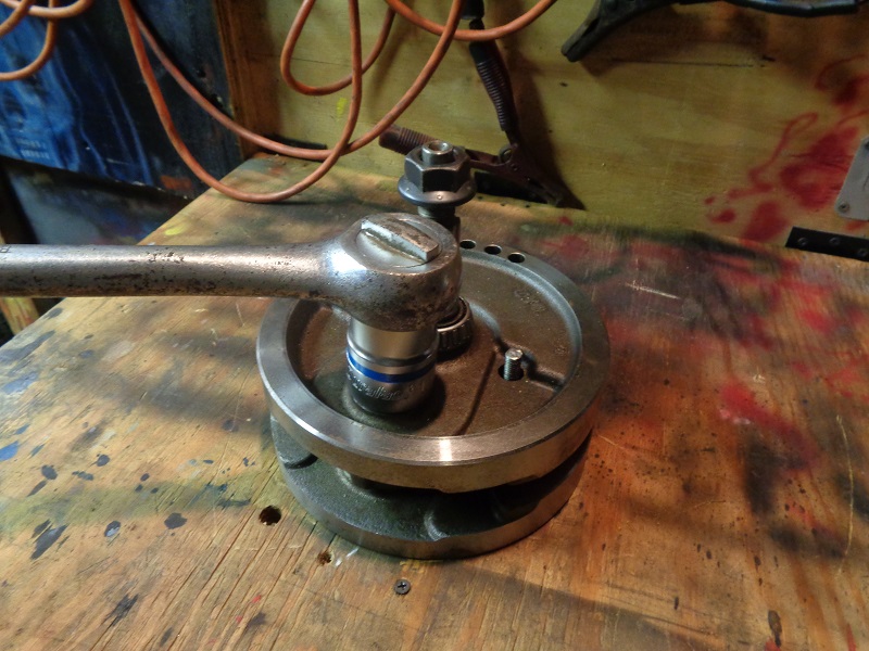
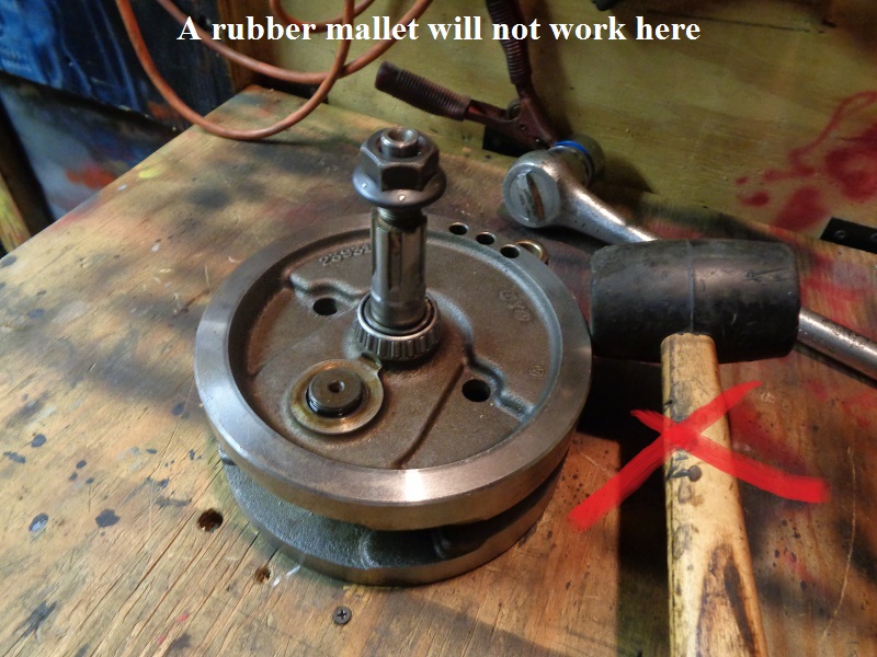
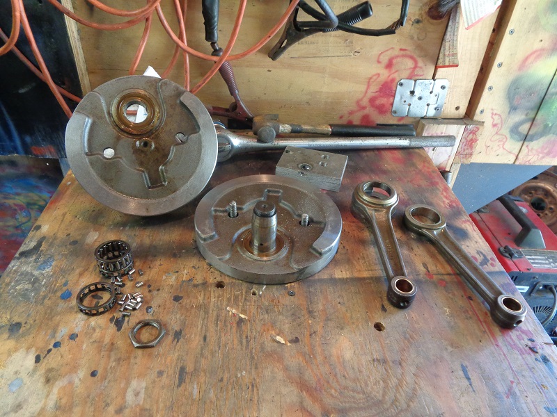
Disassembling the Crankshaft / Flywheel Assembly
This is a 91-99 flywheel assembly but the process is basically comparable for 03 and prior flywheel assemblies.
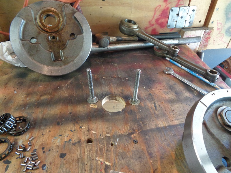
The table is a 3/4“ piece of plywood hinged to the wall with a 2×4 stood up under it.
To make it easier, no measuring of the holes was done.
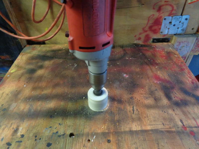
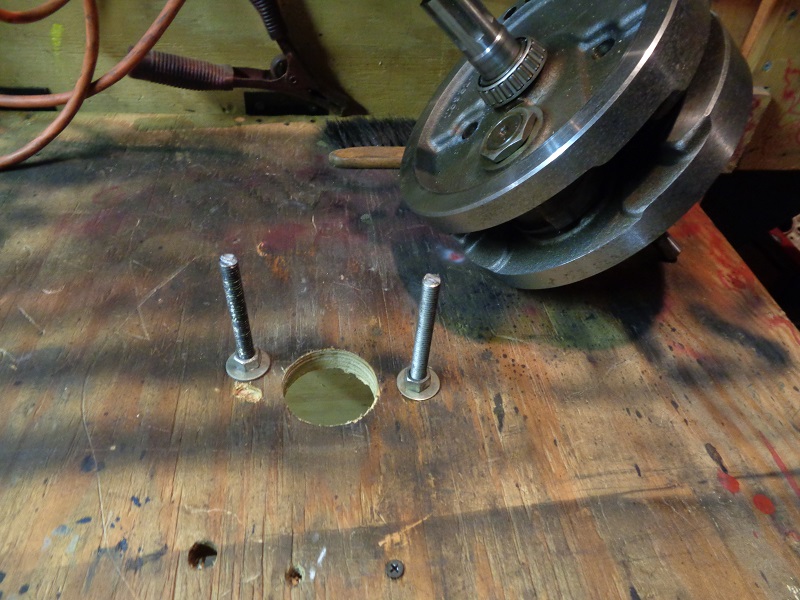
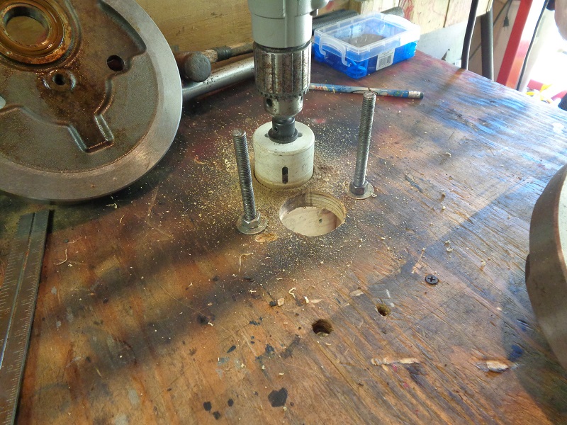
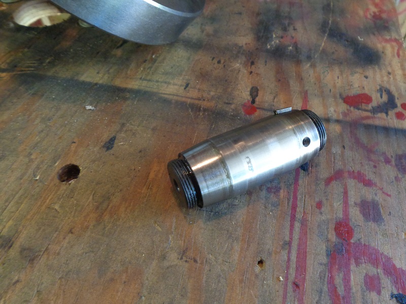
A 2” hole saw was used to bore a hole for the pinion shaft to sit down in.
The size of the hole isn't really critical as long as it's bigger than the shaft.
The 2“ hole just gives some leeway to position the wheels to drill for the holding pins.
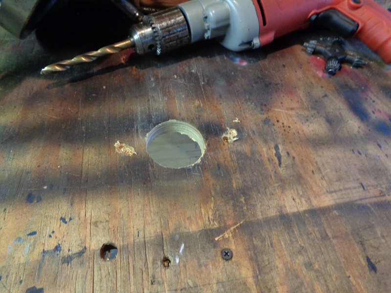
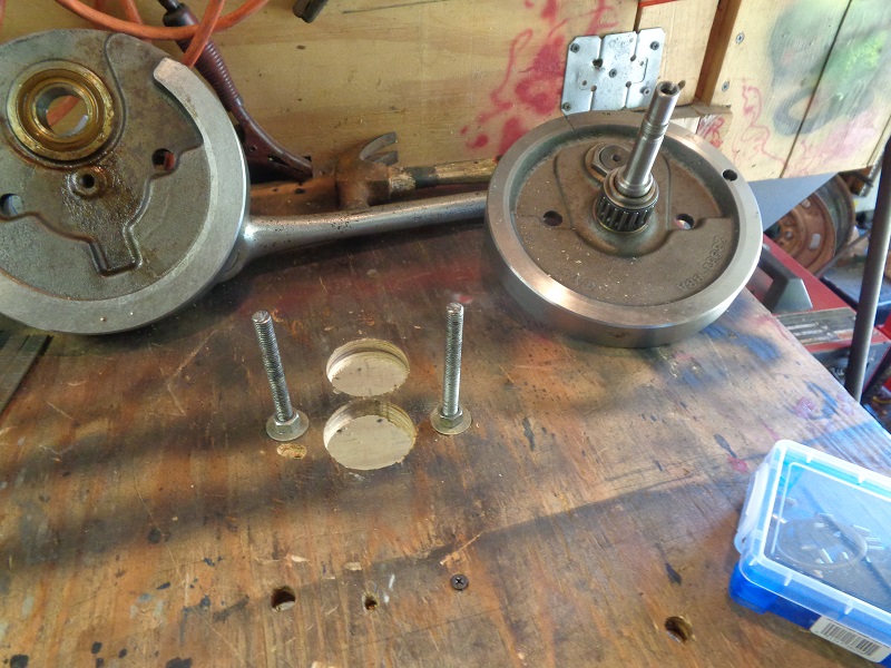
Then a 3/8” drill bit was run into the holes to the board to mark the hole locations.
 | 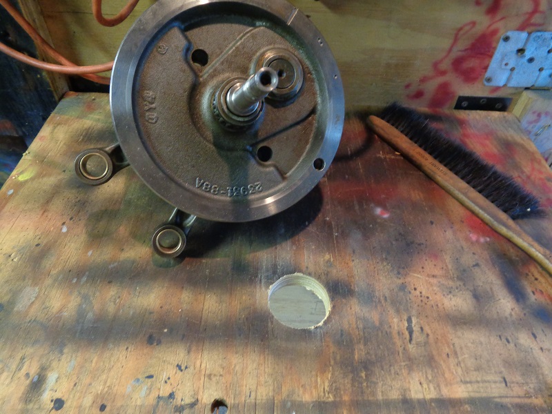 |  |
The location can be adjusted if needed before drilling the holes.
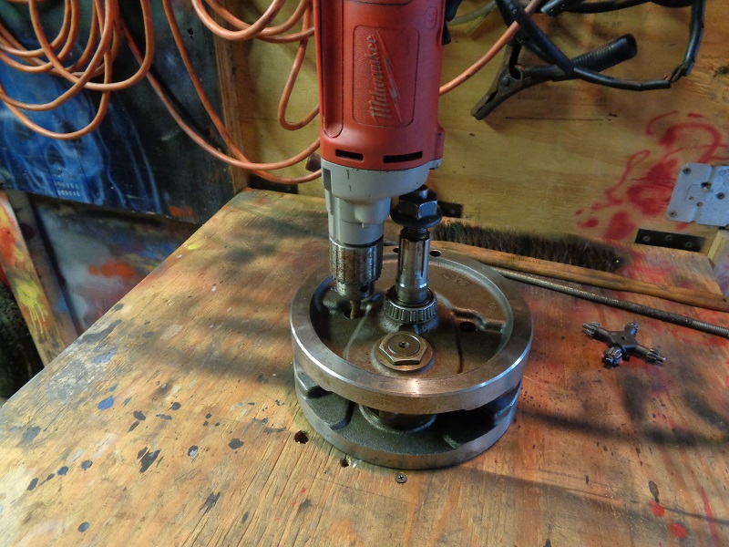
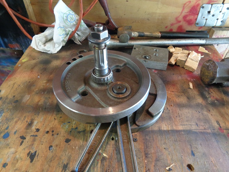
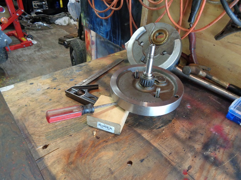
Once the holes are drilled, run 2 pieces of 3/8“ x 12” threaded rod into the holes with nuts and washers on top and bottom.
Make sure they're tall enough to go through the holes in the top wheel.
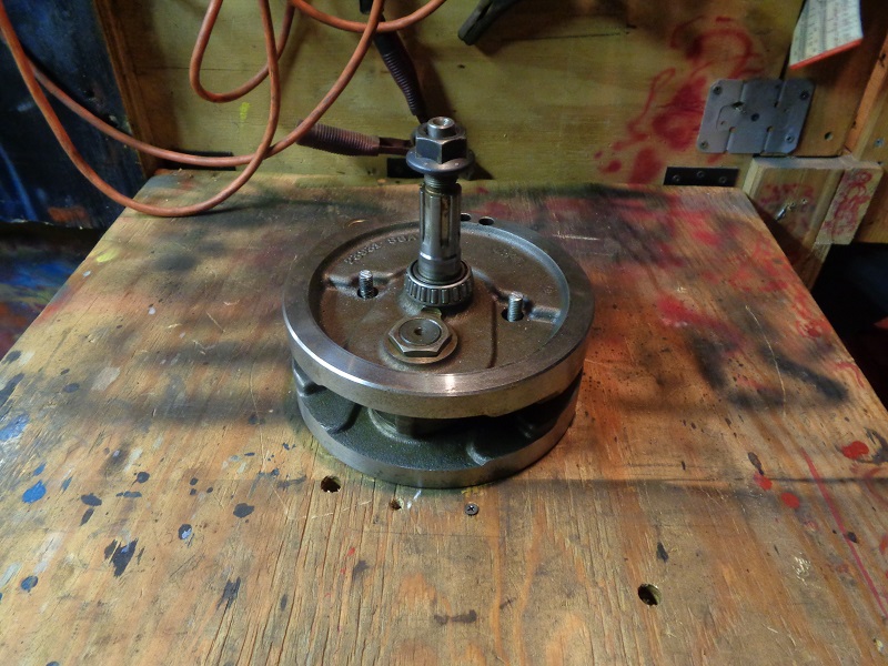
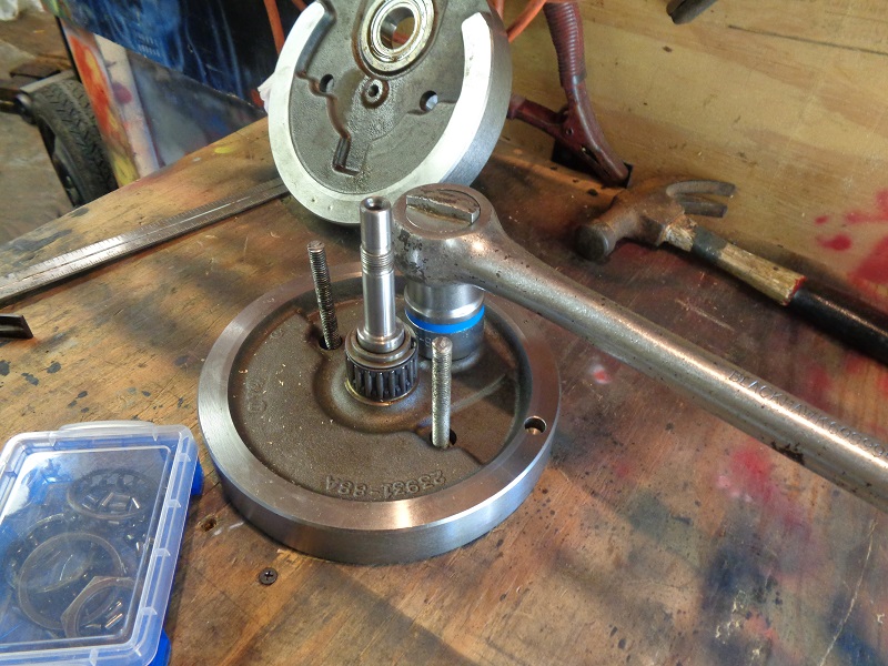
Then set the wheel over the all-thread (or holding pins).
 |  |  |
 |  |  |
 |  |  |
 |  |  |
 |  |  |
 |  |  |
 |  |