Table of Contents

EVO: Carburetor, Intake Manifold & Exhaust
The EVO Sportsters have used Keihin carburetors from 1986-2006. The CV design was used from 1988, with the 1989 models getting an upgraded version with an accelerator pump. Sportster models from 2007-later use fuel-injection.
The following information is most relevant for 1989-2006 models, although many of the principles are applicable to other carbs and other years.
CV40 CARBURETOR DESIGN
Design Info
From 1989-later, the carburetor installed on Sportsters was made by Keihin. Known as the CV40, it has a 40mm maximum venturi, but the design of the constant-velocity carb utilizes a vacuum-operated slide to vary the venturi opening to help maintain a proper air velocity throughout the carbs operating range.
The CV40 uses a gravity-fed fuel supply through a float controlled inlet valve to fill a fuel supply bowl, from which the internal jets obtain fuel. It also has an enrichment system, mislabeled a choke. This provides a pathway for fuel to bypass most of the carb operation and be supplied directly into the manifold, at the rear of the carb, for better starting. There are air passages to the fuel pathways to mix the air and fuel together.
There are a number of parts that operate in combination to control the mixing of fuel & air into a combustible fuel mixture. The vacuum slide, needle, needle jet, emulsion tube, main jet, slow jet (with an emulsion tube), idle mixture screw, idle ports, tranfer ports and accelerator pump, all assist in this mixing operation over the range of operating conditions.
The purpose of the carburetor is to atomize fuel into the incoming air such that a proper air-fuel-ratio (AFR) is achieved for varying conditions. The Slow Jet (AKA Pilot Jet) & Main Jet each use an emulsion tube with a fuel orifice & air holes. Each emulsion tube pulls fuel from the float bowl reserve and is fed air thru small air ports (called air jets) on the face of the carb (filter side). In each case, the emulsion tube produces an air/fuel mixture that is further mixed with the air flowing into the venturi (carburetor throat).
The air flow is generally controlled by the Throttle Plate along with the vertically moving slide that essentially varies the venturi size to create a Constant Velocity of air (from which it gets it's name). By selecting various Slow and Main Jets, the AFR can be altered to produce a preferred ratio. Air flowing into the venturi creates a vacuum which pulls the air/fuel mixture from the emulsion tubes into the air stream.
To create a proper idle operation, the Idle Port (on the engine side of the throttle plate) has a separate adjustable screw (Idle Mixture Screw) that allows some of the mixture from the Pilot Jet emulsion tube to be bled directly into the manifold, bypassing the throttle plate.
As the throttle plate is opened, fuel is pulled from the Transfer Ports. With more throttle, fuel is pulled thru the needle jet, in greater quantity as the tapered needle is lifted out of the needle jet opening by the vacuum-operated slide.
The constant-velocity system provides a partial means of compensating for operation at different altitudes. In a fixed system, as altitude increases, the fuel mixture becomes richer due to the thinner air. But the CV system partially compensates for this fact because the vacuum-slide operation is also affected by the thinner air, thereby supplying less fuel into the mix to match the reduced air density.
The CV40 (1989-later) has an accelerator pump, controlled by a rod attached to the throttle cable cam, to provide additional fuel when the throttle is quickly opened for acceleration. It squirts raw fuel into the venturi throat to enhance the fuel mixture along with the quickly added air.
The stock carb has been adjusted to control exhaust emissions. The idle mixture is set at the factory and the adjusting screw is capped because it is not intended to be adjusted except by factory technicians. However, the cap can be removed and adjustments made as needed.
From the service manual (FYI): Adjusting mixture setting by procedures other than specified in this section may be in violation of local regulations.
Some Tuning Considerations
To obtain a perfect tune, for a specific bike, would require a number of dyno runs with mini-changes done to the timing & carb AFR between runs. Even then, perfection is most often fleetingly confined to a narrow portion of the throttle curve, while the remainder is 'good enough', but not perfect.
With most DIY riders, who wish to tune their own bikes, they don't have access to cheap dyno time and they don't have a collection of needles & jets to perfectly tweak the tune. Instead, they are mostly confined to having one or two needles and a few (maybe 3 or 4) jets to make AFR changes. Timing could be adjusted where there is a cam sensor plate, but after 2004, the timing was held captive inside the ignition module. This required a computer to access and change it or the rider must rely on the local dealer to 'reflash' the latest upgrade and hope the MoCo got it right.
Even so, if done methodically, with careful attention to detail, most DIY riders do get their tune 'close enough' to match the modified air cleaner & exhaust upgrade (generally known as a Stage One upgrade) with just a handful of parts.
Over the years there have been many different approaches to tuning the CV carb - some of them simply distorting the tune to skew it's operation toward some (perceived) 'enhancement' of a specific part of the throttle operation curve. Unfortunately, when most of this advice is followed, the normal street rider is left with 'problem' areas in the overall throttle range and they then use 'trial & error' with many other changes to address those 'tuning created' problems. It doesn't take long to be confused and dissatisfied.
With the collected results of many years of (reported) experimentation, some of the older suggestions have been found to be unacceptable for a good overall carb tune. Therefore, just because it was recommended in the past does not make it a good idea. This is especially true where permanent modifications (damage) are suggested for the stock carb parts. In the XLForum, there is quite a general consensus (although some still disagree) that a well tuned carb for the entire throttle range, is one with NO permamently modified carb parts, but rather, that tuning only uses a change in the needle and jets while carefully making carb adjustments.
An issue created by the factory carb settings, to meet EPA regs, is that the CV carb has often had off-idle (lean) carb farts with the factory tune, which increase after stage 1 modifications. There have been a number of proposed 'solutions' to the carb fart problem (with some of those 'solutions' creating other issues).
Below you will find many collected suggestions that should get a Stage One, 1200cc Sportster properly tuned for a balance of performance and smooth, reliable, street operation. The same principles will apply to 883 models and also to somewhat-upgraded (1250/1275) engine sizes, but altering the jets or needles to meet the needs of each particular engine.
Stock Keihin needles & jets are often critical to a well operating carb. Note these comments by Joe Minton in reference to HD & aftermarket carb tuning kits: “The needle and needle jet in these [aftermarket] kits are made of brass; the stock Keihin needle is polished hard-anodized aluminum, and the needle jet is hard brass. The brass-on-brass of the [aftermarket] kit wears quickly and further richens an already too-rich mixture. The stock parts hardly wear at all. I have examined stock needles and jets with 45,000 to 70,000 miles of use and could not detect measurable wear.”
Trust the Keihin parts to provide good service and avoid problematic aftermarket kits.
WORKING WITH CV40 CARBURETORS
 |
|
 |  |
Diagnosing CV Carb Issues
Eliminate Intake Air Leaks Mounting the CV Carb properly is critical. Check when mounting (or remounting or having issues with) the carburetor that the alignment between the carb and the manifold is correct. The reason this is so important is because misaligned mounting will cause tuning problems because any leaks will alter the Air-to-Fuel Ratio.
Before inserting the carb into the manifold rubber seal, apply a very light coating of oil around the inside of the rubber seal - This helps prevent the rubber from distorting during the insertion.
Use a bracket to actually mount the carb to the cylinder-heads - Don't just hang it on the manifold.
If you are using breather bolts (1991-2006), insert them through the banjo fittings - with sealing washers on either side of the banjo fittings - Then through the mounting bracket and into the cylinder-head mounting (breather) holes - add washers behind the bracket to take up any additional space that remains between the support bracket and the cylinder-heads…
See the section titled "Mounting the CV Carb - Preventing Air Leaks"
This process will give you a good rigid mount of the carb to the cylinder-heads while maintaining a good alignment of the carb with the manifold, all working together to eliminate those pesky intake air leaks.
1)
Check the Slide Diaphragm - Be sure the slide operates correctly & the diaphragm is not torn or punctured. To do this, remove the air cleaner and reach your finger into the carb throat to the slide - push the slide up and quickly let the slide fall down. You should hear the vacuum sound as the slide returns to the bottom position.
This is from an XLForum thread: chrishajer wrote - CBAS5 and I were talking about what it should sound like, good, and we filmed that one. Then he said “you know, we should show a bad one too” so we did that. I think the [vacuum] sound and the speed that the slide comes down are the two most important things. Those things you can't describe to someone really. I can't anyway. But it's absolutely the best way to verify that the diaphragm is seated properly.
Youtube Videos of:
The Sound of a GOOD working slide ………
The Sound of a MALFUNCTIONING slide
Aftermarket Parts are promoted as upgrades to peak the carb performance. Sometimes they do create better performance for one part of the carb operation. But most often, they simply distort the proper overall performance and create ongoing issues that are difficult or impossible to resolve. If you're racing, the setup for normal street operation may be irrelevant, but for most riders, getting good performance in all conditions is important. Keep this in mind when evaluating any promises of upgrade products.
Mixing Parts from various carb kits (such as needles, emulsion tubes, springs, etc.) can lead to major issues when trying to get the tuning right. A mix of parts may lead to one particular operation working correctly while nearly always disturbing the proper functioning of the carb across the entire operational range, from idle to WOT. Do not mix parts. The OEM/Keihin parts allow a proper tune with only minor changes to the jetting or needle choices.
Slow jets from fixed venturi carbs look the same as the ones used in CV carbs. However, the air bleed hole sizes are different on fixed venturi carbs and must not be used in CV carbs. 2)
Before Tuning - Collect Your Information
To prepare for tuning, start by checking what parts are in your carburetor. The factory jets and slide tube may have been altered to aftermarket parts. Some aftermarket parts are not compatible with factory parts. When buying rebuild kits, there may be extra parts not needed for your particular carb model.
When tuning, it is often less expensive to just buy the parts you actually need rather than tuning kits, which can get pricey. So planning ahead is a good idea. Know what you have before buying additional parts.
Why Not Dynojet Kits?
The “DynoJet” kits (and many equivalent ones) can be an issue. Typically, they replace the factory needle, emulsion tube, main jet & diaphragm/slide spring. They also recommend that you drill the slide vacuum hole out for quicker throttle response. The DynoJet emulsion tube and main jets are not compatible with the Keihin emulsion tube/jets - they use different threads. There are even FAKE Dynojet kits that have shown up on the market, presumably from China 3)
More info & links here: SubDoc - Why Not Dynojet Kits?
To check for DynoJet parts, look at these 4 things: 4)
- Check the Needle: Stock is Nail-shaped - DJ has grooves & a clip
- Check the Diaphragm/Slide Spring: Stock is 6.0“ - DJ is 5.75”
- Check the Slide Vacuum Port Hole (not the center hole): Stock is .097“ - DJ is .136” (Is the hole smaller or larger than 7/64“ drill bit?)
- Check the Main Emulsion Tube : Stock has 2x2Hi+4x3Lo Emulsion Holes - DJ uses only 2Lo Holes
- The stock Keihin Emulsion Tube uses 6mm-threaded Main Jets - The DJ one takes only 5mm-threaded jets, which are incompatible with the Keihin tube and only available from DJ
Here's the Dynojet Fraud Alert Press Release regarding counterfeit jet kits:
dynojet-pressrelease-knockoffjetkits.pdf
While some people have had satisfactory results with the DJ kits, if you are having trouble getting a good tune on the carb, remove all DJ items and restore the carb to Keihin parts including buying another slide if it's been drilled. The stock parts are good quality and will provide excellent operation if the carb is tuned properly. 5) See the paragraphs above about 'Some Tuning Considerations'.
CV40 Needle, Jets & Idle Mixture Screw Parts
| Here are the genuine Keihin CV40 parts. Check your parts to be sure they match. | Be sure the Needle Jet is installed with the long side up into the carb throat. | These are the parts for the Idle Mixture Screw (IMS). |
 |  |  Assemble in Correct Order Onto IMS Needle pointed up, put the Spring, then Washer, and O-Ring goes on top. |
From the factory, there is a cap over the Idle Mixture Screw. This needs to be removed to make IMS adjustments during tuning. It does not need to be replaced when done, but the cap is available as HD P/N 28015-01 if you would like to replace it when done making changes.6)
The Idle Mixture Screw “packing” (spring, washer, o-ring) and the screw itself was never meant to be removed or tampered with, according to the MoCo, due to EPA regulations. This was adjusted and the screw covered with a soft aluminum cap at the factory before initial installation on your bike. None of these packing items are offered as replacement parts from your HD dealer, so you will need to look to the aftermarket suppliers for parts.
To remove the IMS cap, carefully drill a small hole in the center of the cap (barely enough to make a hole). Be extremely careful not to overdrill into the cap because you will damage the screw that is behind the cap. Now, carefully twist in a sheetmetal screw about one thread, then pull on the screw to remove the cap.
An aftermarket kit (like E-Z-just) can be purchased with an extended screw head for hand tuning. It comes with the “packing” in case yours has been damaged or is not functioning properly. But, check your local regulations before changing this out to an aftermarket part. You can also find, buy or barter for used parts. (“Please note: it is a violation of federal law to tamper with or disable any emission or noise control device. That is your PSA for the day”7) 8).
Checklist Of What You Have - In order for others to provide quality advice, it is important that you know and can provide quality information about the build of your bike. Here's a list of important information for you to know and provide for TUNING of the CV carburetored EVOs (1986-2006):
| Review These Considerations That Affect Tuning The CV40 Carburetor | |
|---|---|
| Device Question | These Are Possible Answers - Be Specific About Your Config |
| Engine Size | (Stk883, Stk1200, Stk1100, Stk900, Stk1000, Conv883-1200, Conv883-1250, etc.) |
| Heads Installed | (Stock 883, Stock 1200, Specify Brand/Model) |
| Cam Installed | (Stock D, Stock W, Specify Brand/Model) |
| Compression Test | ( Min120PSI for 883 - Min150PSI for 1200 - 2004+ Min180PSI for 1200 ) |
| Ignition Module | (Stock 883, Stock 1200, Specify Brand/Model#) |
| VOES being used | (Y/N) |
| VOES Vacuum Mod'd | (Checked/Changed the Switch Point?) |
| Air Cleaner | (Stock, Specify Brand/Model) |
| Breather Venting | (Head Into Carb, Head Out to Air, Crankcase) |
| Exhaust | (Stock, Specify Brand/Model/Baffles/TqCones) |
| Spark Plugs Used | (Stock, Specify Brand/Model#) |
| What Model Carb | (Stock CV, Specify Brand/Model) |
| Check for Intake Leak | (Y/N) (Use UNLIT propane torch near manifold ports) |
| Petcock | (Stock Vac, Modified, Specify Brand/Model#) |
| Vacuum Line Checked | (Y/N) |
| Enrichener Cable Seated | (Y/N) |
Inside of CV Carburetor:
| Slow Jet | (Stock, Specify Known Size) |
| Idle Mixture Screw | (Set at xxx full turns from lite seat) |
| IMS set by Idle Drop | (Y/N - Did you change it?) |
| Drilled Slide? | (Y/N - Based on who's recommendation?) |
| Altered Slide Spring? | (Y/N - Based on who's recommendation?) |
| Jet Needle | (Stock, DJ, Other Keihin, Specify Brand/#) |
| Emulsion Tube | (Stock, DJ, Specify Known Brand/#) |
| Main Jet | (Stock, DJ, Specify Known Brand/Size#) |
| Fuel Float Level Set | (Y/N - Stock, Other) |
| Fuel Float Valve | (Y/N - Cleaned & Checked, Replaced) |
 TIP - Do you have an 883 or 1200 size engine? 9) TIP - Do you have an 883 or 1200 size engine? 9)  If you don't know your engine size, check it with a straw - Like this: * Put bike on lift or otherwise raise rear tire * Put transmission in 5th gear * Remove both spark plugs * Place a long plastic straw, chopstick, etc. in the spark plug hole * Rotate tire to move cylinder to bottom dead center - lowest straw position * Measure the cylinder diagonal dimension * Check from far bottom of cylinder to top lip of spark plug hole * If 883 bore then 5.5” Diagonally —- (Actual Bore Dia. is 3.000) * If 1200 bore then 5.875“ Diagonally - (Actual Bore Dia. is 3.498) Straw won't damage the cylinder and unlikely to fall into the cavity. |
Before Tuning - Setup Everything Else
Following an organized and thorough PreOp and Parked checklist will help you understand what you observe when you actually begin the operational testing of the carb during rides…
Here's my suggested list (for 1200 models, although 883s should be mostly the same except maybe the initial jetting) - Even if you've done some of these, being orderly and thorough, doing everything on the checklist will have benefits, especially if you've made changes since your last efforts at tuning…
Check Items Ahead of the Carb
- On later models check for DTCs - These codes can indicate problem areas
- Check your vacuum lines for good connection & no cracks
- Check your VOES - that it switches with vacuum - later check switching point
- or check your MAP sensor to be sure it is operating correctly
- Check your gas tank for debris - remove & clean if needed
- Check your petcock for leaks (bad diaphragm) - Make sure vacuum petcocks open on vacuum
- Check gas line & connectors for wear/breaks/pinches
- Check your petcock for flow rate - Pull the hose from the carb, open petcock (draw vacuum if needed)
- How long does it take to flow one quart (32oz) of fuel?
Internal Carb Checks
- Carefully disassemble carb and all parts - Clean the carb body & each part
- Spray *ALL* ports, passages & jets - Get everything clean to start
- Check your float bowl - clean passages - remove any debris - set/check float level (see below)
- Use only the 4-sided type Float Bowl Valve (not the 3-sided type)
- I prefer eliminating any non-Keihin parts (ie., dynojet kits, etc.)
- (DynoJet Kits may have changed jets, needle, spring, drilled diaphragm, etc.)
- Check/Clean Emulsion Tube (which holds Needle Jet in place and mounts Main Jet)
- Pull Needle Jet - Make sure it's clean & properly installed (Long Side Up)
- Start with 175 or 180 Main Jet in Emulsion Tube (not critical until WOT settings)
- Start with 42 or 45 Idle Jet - Do not start with 46 or more - change later if needed
- Higher altitudes require less fuel for correct AFR - Jets may need reducing for altitude
- Use a standard Keihin needle in slide (no washers to start) (1200 likes N65C Needle)
- Use stock spring & needle cage (spider)
- Check Diaphragm condition - no tears - seat it carefully (properly) on install
- Check Slide moves smoothly up & down with no burrs or catches
- Check Accelerator pump - Point spray hole directly at main needle
- Be sure to reinstall pump rod correctly
- Be sure you have removed each part, cleaned the ports & reinstalled correctly
- Set the Idle Set Screw (located on the right side of the carb, near the throttle cables)
so that the Throttle Plate is closed as much as possible. Try getting it between the Idle Port
(one hole in the carb throat) and the Transfer Ports (which consists of 5 holes nearby).
Don't obssess over it if you can't.
Setting The Float Level
(TIP: Using a 1/2-inch spacer to lift the float side of the carb will approximate the 15°-20° angle needed.)
Click on the small image below for a larger version of the detailed instructions regarding setting the float level:
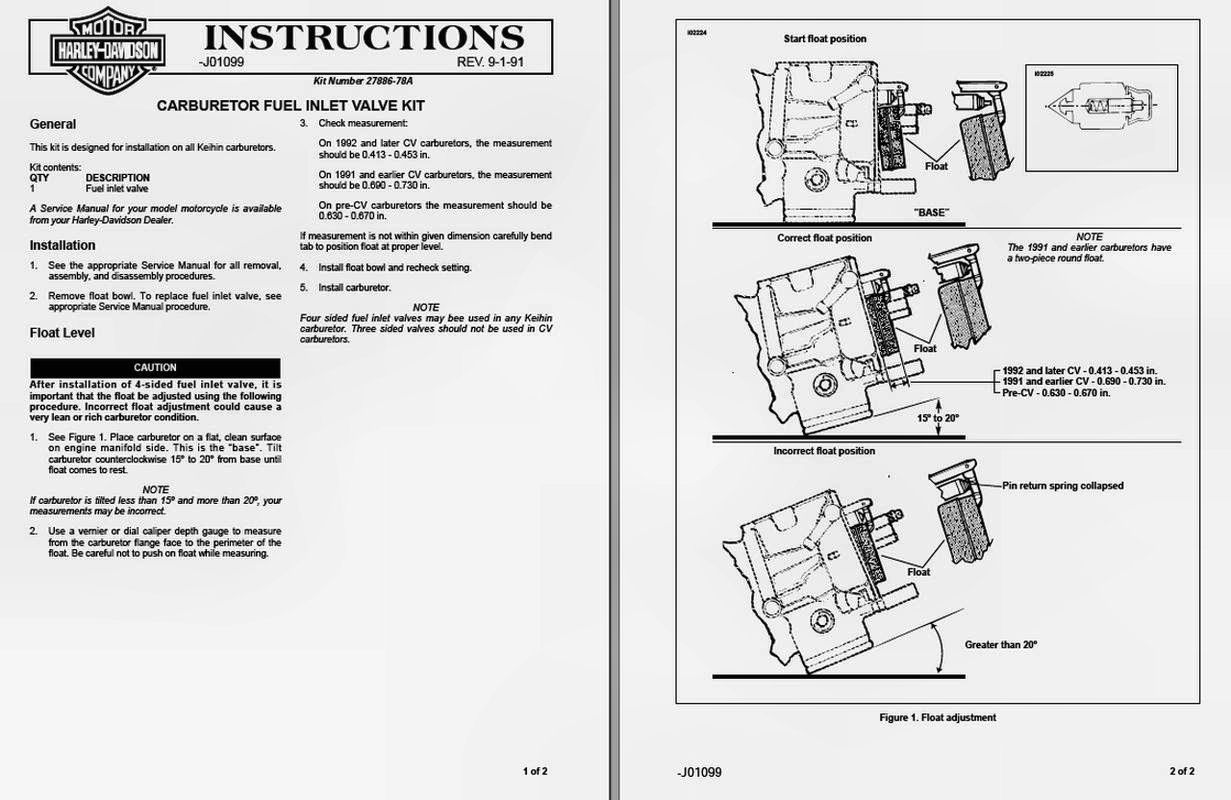


In This XLForum Thread there is a discussion of the float bowl overflowing and the possibility that it is caused by aftermarket float valves that are not of the proper design.10)
Tip for Checking Fuel/Float Level - With Carb Installed
HD advised of a tip for adjusting the float level thru Tech Tip #36 dated September 1993.
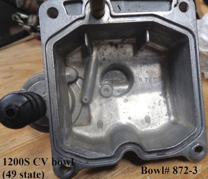
However, this only works if you have an overflow fitting on the bowl (carbs for 1200S models don't have this fitting).
- Checking carburetor float level can be easily done without even removing the carburetor from the motorcycle.
- Simply attach a section of clear model airplane fuel line to the float bowl overflow fitting.
- A small diameter fuel line, which is compatible with gasoline, can be found in most hobby supply shops.
- Route the hose upward alongside the carburetor body.
- The motorcycle must be held level and be running to perform this test.
- Open the float bowl drain screw and fuel will rise in the hose to the same level as that in the bowl itself.
- In a carb with a properly adjusted float level the fuel level in this hose will be at the joint between the carb body and the float bowl face.
External Carb Checks & Adjustments
- Check intake seals on manifold (at heads) - replace now while it's apart
- Check intake seal between manifold & carb - replace now
- Minimize Throttle Plate opening at idle - Set it between Idle Port & Transfer Ports if possible (See this XLForum thread)
- Check Idle Mixture Screw (IMS) screw/spring/washer/o-ring condition - clean port
- Check IMS seat (Has the screw needle tip deformed the hole?)
- Set initial IMS to 2-1/2 full (360°) turns out from lite seat
Change the Screws
Replace the mounting screws used for the float bowl and for the diaphragm cover. They come with Japanese JIS metal head screws. These are similar to Phillips head screws but the JIS screwdriver has a more blunt nose and the Phillips screwdriver will not properly bite onto the JIS screw heads.
Replace these JIS screws with Stainless Hex Socket Head (Allen Head) Screws. Using lock washers & flat washers in stainless is also a good idea. Both sets of screws are 4mm Dia X .70 Thread Spacing. The socket head screws take a 3mm hex wrench.
You'll need (4) screws that are 16mm in length for the float bowl. Then you'll need (3) screws that are 16mm in length and (1) screw that is 20mm in length for the Diaphragm Cover. If you choose to use Button Socket Head Screws for the top cover, they use a 2.5mm hex wrench.
You can also replace the (3) Accelerator Pump screws with 4mm x 10mm long. 11)
Summary List:
Click Here for a full screw list on the fastener page in the Sportsterpedia.
4ea - 4mm x 16mm x .70TPI for Float Bowl
3ea - 4mm x 16mm x .70TPI for Top Diaphragm Cover
1ea - 4mm x 20mm x .70TPI for Top Diaphragm Cover at Throttle Bracket
3ea - 4mm x 10mm x .70TPI for Accelerator Pump
Hex Socket Head bolts use 3.0mm hex wrench
Button Head bolts use 2.5mm hex wrench
( Also see: XLF Thread 1, XLF Thread 2 & XLF Thread 3, XLF Thread 4 )
As a reference, here are the OEM parts for the Carb Top Cover:
| 1988-1996 OEM Parts | |
|---|---|
| Part No | Descripton |
| 27040-88 | CARBURETOR TOP COVER |
| 27129-88 | SCREW, TOP (3) |
| 27317-88 | SCREW (Top 1 for bracket) |
| 1997-2006 OEM Parts | |
| 27261-96 | CARBURETOR TOP COVER |
| 27262-96 | SCREW, TOP (3 shoulder bolts) |
| 27587-88 | SCREW (Top 1 for bracket) |
| 27263-96 | COLLAR (for bracket hole) |
If you replace the screws on models that used a shoulder bolt, be careful not to overtighten the screws or you may crack the corner of the cover. Here's a video regarding installing brass ferrules when replacing the screws, should you choose to go that far. 12)
Reinstall Slide, Diaphragm & Cover
To prevent tearing the Slide Diaphragm (reinstalling) - Shu: 13)
- Use four small dabs of wheel bearing grease in the seal channel spaced between the screw holes
- Drop the slide into the carb (with needle, spider & spring in the center)
- Reach inside the throat of the carb and raise the slide up a bit to lessen the tension at the seal
- Seat the diaphragm seal in the channel of the carb
- Install the carb top cover, centering the spring in the cover (while still holding the slide up)
- Install the top screws (while holding the cover in place)
I've done it a ton of times on many carbs and never ripped a diaphram.
The problem comes when you try to do this without holding the slide up.
Reinstall Carb & Air Cleaner
- Be sure to use light oil coating on intake manifold seal to help slide carb into place
- You MUST use (some type of) a bracket to actually mount the carb to the cylinder-heads
- Check that mounting the carb does not disturb its position in the manifold
- Reference the section titled ”Mounting the CV Carb - Preventing Air Leaks“
- BE SURE to check that your throttle cables fully open & close the Throttle Plate!
- If your heads use breather bolts - Use external head breather system to eliminate oil in air cleaner & cylinders
- Do not lubricate the enrichment cable (misnamed Choke) on CV Carburetors - tension is needed. 14)
IDLE & TRANSFER TUNING ADVICE
Overview
- ALL TUNING should be done after the engine has warmed up thoroughly - Try a 10-15 minute ride
- Check carburetor-to-manifold-to-heads for air intake leaks - Unlit propane torch will alter idle
- Be sure the Enrichener Knob is fully closed
- Set the IMS - See the “Idle Drop Method” mentioned below
- After tuning, adjust Idle Set Screw so bike idles well at 950-1050 RPMs
Check Accelerator Pump
- Check Accelerator pump - Twist throttle, see that it squirts directly at the needle
- See the expanded explanation of the Accelerator Pump operation listed below
Check Transfer Operation
- Check Response to Blipping the Throttle (while parked) - should be crisp & responsive
General Comments about Idle/Transfer Tuning
Every bike/engine/carb/exhaust combination functions a little differently, so tuning the carb must be done while monitoring the engine response. All the parts must work correctly so it's best to check & set some parts before starting the tuning. This can prevent distortion of the carb operation and your results.
Because of the constant-velocity design, where the vacuum slide works as a partner with the throttle plate, the throttle being wacked open DOES NOT equate to the carb operating at wide open. The vacuum slide responds to the throttle plate opening, and increases the size of the carb venturi, in response to the change in vacuum. More vacuum in the slide chamber, ahead of the open throttle plate causes the slide to create a larger venturi. In essence, the vacuum slide makes the CV carb operate as a variable-venturi carb, because the size of the throat opening is altered by the vacuum slide rising & falling.
- Reference the pictures above & below to identify the various parts during the explanation of their operation.
The Idle Port is intended to supply the necessary fuel mix (AFR) when the engine is idling, but it also continues to help feed a fuel mix during the transfer operation and minimal speed cruising. The Transfer Ports are intended to add more fuel mix when the throttle plate begins to open during the period between idling and the mid-range operation of the engine. If the throttle is opened quickly, the Accelerator Pump will supply a shot of fuel to mix with the increased air passing thru the venturi.
The Transfer Ports continue to actively supply fuel for the carb operation, although, as the throttle/slide/needle increase the engine speed, the Transfer Ports represent a smaller & smaller percentage of the overall fuel supplied & consumed. However, when cruising at a minimum speed (with the throttle plate barely open), the Transfer Ports are an important part of supplying fuel for the carb operation, along with the needle in the needle jet.
The mid-range operation is mostly handled by the needle position in the needle jet, followed by the main jet metering fuel when the throttle/slide/engine is operating at Wide Open Throttle, with the needle fully retracted from the needle jet.
The selected needle effects the overall operation of the carb. Plus, initially, you don't want the Main Jet to cause any lean conditions while you're riding the bike to verify idle & transfer operations, so the Main Jet should be at least a 175 or 180.
The needle is also important relative to testing the transition between idle & mid-range throttle operation because you are transitioning to using the needle. There were many different needles and main jet combinations supplied on various models. Making modifications to air cleaners & exhausts also present a myriad of different conditions. Sometimes, using the stock needle is fine for getting the right AFR across the operating range. This is often true with the 883 models. Other times, you may need to replace the stock needle with an N65C needle (which creates a better overall AFR than the stock needle) since it has been found to work well on 1200cc models. Experimenting with other needles or raising the base level of the needle with washers is a common way of altering the AFR for the mid and upper range operation of the carb.
After getting the idle & transfer operations set correctly, you will need to verify whether the needle & main jet selections work properly over the entire carb operation range. You can use tuning methods for mid-range and wide-open-throttle operation to evaluate your choices.
Descriptions of the Operating Parts
Main Jet - The Main Jet itself does not begin to limit fuel delivery to the carb operation until the vacuum slide is 75-90% wide open and the engine is revving. Until then, other parts & factors (such as the idle mixture screw, slow-jet and needle position in the needle jet) are controlling the fuel utilized by the carb.
Needle & Needle Jet - The needle is a tapered, nail-like, rod that operates from the bottom of the slide into the needle jet. It does not affect the flow of fuel until the throttle plate opens sufficiently to create an active vacuum in the outer section of the venturi, which will lift the slide and move the needle in the needle jet. The fuel mix supplied thru the needle jet, by your selected needle and the emulsion tube, will combine with the transfer fuel mix of the slow jet as the carb operation moves out of the transfer period into the mid-range of the throttle/slide function.
The main jet, located at the bottom of the emulsion tube, is way below where the needle rides. It has no variable relationship with what the needle does except to create an eventual upper fuel limit at WOT, when the needle is fully out of the needle jet. 15) The needle rides in the needle jet which is the silver colored jet (hollow cylinder) that sticks up from the bottom of the throat of the carb. The tapered needle moves up and down thru this constant orifice during the vacuum slide operation.
The space between the needle and needle jet control fuel flow coming out of the emulsion tube into the throat. After the needle is out of the needle jet, then the main jet will become the limiting factor for the fuel flow at the wide open throttle position (WOT). Until the needle gets out of the way, the main jet is doing nothing to limit the needed fuel.
Significant Comment by Don Burton from this detailed discussion of some of the needle dimensions at this interesting XLForum Thread:
“Also, elsewhere someone has measured the inside diameter of the needle jet (the needle jet, not the jet needle) as being just .114 of an inch. If so, that explains why just .001 of an inch difference in diameter of the straight portion of the needle (usually measures between .107-.110, depending upon the needle) makes a significant difference in air/fuel ratio at just above off idle and in the lower throttle settings.”
Emulsion Tube16)- As the throttle plate is opened further the main circuit comes into play. Fuel enters the bottom of the emulsion tube thru the main jet. Air enters thru the main air bleed jet in the front of the carb. The air and fuel are mixed in the emulsion tube before this fuel mixture passes up the tube past the needle jet and needle into the carb venturi and down the intake chasing after (combining with) the idle circuit fuel mix. The size, number and position of the holes in the emulsion tube effect the fuel delivery. More holes = more air = leaner mixture. More holes at the top = leaner mixture at low speeds. More holes at the bottom = leaner mixture at high speeds. If you change emulsion tubes you need to use a compatible needle. It will also have an effect on the main jet size (at WOT) and quite often the pilot circuit thru the just-off-idle response. Needles, needle jet, emulsion tube (size, position and amount of holes), main air bleed size and main jet are all closely linked. Changing one can affect the others and all have an affect on the fuel delivery to differing amount at different throttle positions.
Throttle Plate - To assure the throttle plate is capable of closing completely, back out the idle set screw (on the side of the carb near the throttle cable cam) so that it is not limiting the closing of the throttle plate.* Make sure the throttle plate rotates smoothly with the throttle cable cam. Set the position of the throttle plate, with the idle set screw, so that the bottom edge of the plate is closed as much as possible for setting the idle operation. Try getting it just past the transfer port holes and thus located between the single idle port hole and the multiple holes of the transfer ports. In practice, this is easier on some CV40 carbs than others. Do what you can to keep the plate as closed as possible, but DON'T OBSSESS on getting it exactly between those port holes. Your viewing angle is skewed when opening the throttle plate and looking in the venturi, anyway, so you see the hole before the plate is completely beyond it.
(* It doesn't happen often, but if the throttle plate appears not to close fully with the idle screw fully wound out, it may need to be recentered in the throat. Carefully loosen the two throttle plate mounting screws, slightly. After the throttle plate is fully closed and has centered itself in the venturi, start to retighten the two mounting screws (don't overtighten & strip the threads) while opening & closing the throttle so the plate squares up with the shaft but also recenters in the venturi. If by chance, for any reason, you have the throttle plate completely off, be aware that there is a right & wrong way to reinstall it. Be sure the plate is remounted with the right orientation because the top & bottom have an angled edge that needs to properly meet the carb venturi.)
 IMS Cap - From the factory, the cavity for the Idle Mixture Screw (IMS) is covered with a small cap. (Note from the service manual: Adjusting mixture setting by procedures other than those specified in the manual may be in violation of local regulations.) The following procedures are not specified in the manual. To remove the cap and gain access to the IMS, use a small drill bit to create a hole in the cap. Use several layers of tape on the drill bit to limit the depth the bit can penetrate the cap. If you pop thru the cap too deep with the bit, you may damage the internal screw head - Be Careful. Once your cap has a hole in it, CAREFULLY thread a self-tapping screw (blunt nose) into the hole JUST ENOUGH to capture the cap & pull it out of the IMS cavity.17) If you want to replace the cap, it is HD P/N 28015-01.
Slow Jet, Transfer Ports, Idle Port & Idle Mixture Screw - As illustrated below, these parts function in a close relationship. The size of the Slow Jet creates a fuel mixture that is delivered to the Transfer Ports (5 openings), but is also flowed to the Idle Mixture Screw (IMS). The IMS is adjusted in small increments to allow some of the fuel mixture (from the Slow Jet) to be flowed thru the Idle Port (one opening). In this way, while both the Idle Port & the Transfer Ports are dependent on the Slow Jet, the amount of fuel to the Idle Port fuel can be controlled separately from the Transfer Ports by using the Idle Mixture Screw. A more detailed description of this operaiton follows this brief overview.
Note: There is an XLForum discussion thread regarding the relationship between the Transfer Ports and the Slow Jet (AKA Pilot Jet): https://www.xlforum.net/forum/sportster-motorcycle-forum/sportster-motorcycle-intake-and-exhaust/sportster-motorcycle-air-intake-carburetor-efi-fuel-and-exhaust/151434-cv-carb-transfer-ports?t=1635658 18)
![]()
![]()
Interaction of Jets & Ports - A Balancing Act
The Slow Jet (AKA: Pilot Jet or Idle Jet) along with the Idle Mixture Screw (IMS) determines the quantity & quality of the Idle Fuel Mix, while the Slow Jet alone determines the Transfer Fuel Mix. It is an important balancing chore to get all the parts involved in the Idle & Transfer functions to work well together to meet the needs of the engine operating range. As you change one part or setting, it may require making changes in other settings in order to keep or find the proper balance of the different fuel circuits. This balancing concept also applies to the mid-range and wide-open-throttle operations.
The Transfer Ports rely on the properly sized Slow Jet for the Transfer Fuel Mix, especially since there is no other adjustment available to control that mix. This is an important consideration because the Transfer Fuel Mix is not only active during the brief period of transition between idle and acceleration, but is also active during the much longer period of minimal speed cruising, where the throttle plate is mostly-closed.
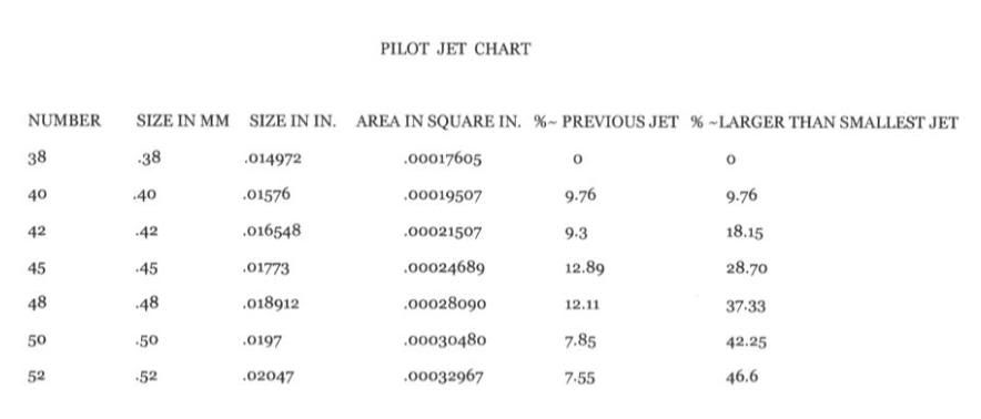
For this reason, it is important to guess-timate the proper Slow Jet before beginning your tuning. The most often supplied factory Slow Jet is a 42, although there are a number of models with a variation from that. If your model is an 883 with the stock air cleaner and exhaust system, that stock slow jet might be fine to begin tuning. But if the air cleaner & exhaust have been upgraded (Stage One) or you have a 1200 engined model or beyond, it is generally recommended to increase the Slow Jet to a 45 before beginning your tuning. In some cases, the aftermarket 44 size may do well, but it has been found that the 48 size Slow Jet is almost never needed for proper tuning. Actual tuning is the right way to determine the final jet selected.
At idle, the Idle Port is supplying Idle Fuel Mix on the engine side of the throttle plate where the vacuum is high. The Transfer Ports are on the air cleaner side of the throttle plate where the vacuum is low or equal to the ambient air pressure - and fuel is not being supplied from here.
The Idle Mixture Screw (IMS) is used to meter the idle fuel mix into the Idle Port (that one little hole). Looking from the bottom of the carb upward, the IMS is turned counter-clockwise from GENTLY seated (fully closed) to increase the flow of Idle Fuel Mix into the Idle Port orifice.
The raw fuel for the fuel mix comes thru the Slow Jet and mixes with the fresh air from the Slow Jet Air Vent (located at the mouth of the carb). This fuel mix is being supplied past the Transfer Ports (inactive at idle) to the Idle Port, where the IMS will control the amount of fuel mix delivered into the carb venturi and thereby into the engine intake manifold.
Because the richness of the fuel mix is controlled by the Slow Jet, which incorporates an emulsion tube to mix fuel & air, the size of the Slow Jet has a direct effect on the proper setting of the IMS. When the Slow Jet is enlarged, the IMS (& Transfer Ports) gets a richer mix and a lower number of turns open (on the IMS) will provide the same richness (as with the previous jet & larger IMS setting).
Having gained access to the IMS, it is recommended that you start by opening the IMS from GENTLY seated to 2-1/2 full (360°) turns CCW. This setting is likely to be larger than the factory setting, which is often in the 1 to 1-1/2 turns range. By opening the IMS more, we are richening the Idle Fuel Mix to provide addition fuel during idle & transfer operations.This may also help the engine run cooler.
Thus far, the throttle plate has been positioned (as much as possible) between the Idle Port & the Transfer Ports, the Slow Jet has been chosen as stock or a 45 if the engine is 1200 or Stage One, the IMS cap was removed and the IMS was adjusted to 2-1/2 full (360°) turns out from GENTLY seated. In addition, a selected needle was installed in the slide along with a reasonable choice for the Main Jet. These parts and settings were selected to provide a valid STARTING POINT for further, more accurate, adjustments.
While the proper idle rpm will be set AFTER adjusting the IMS setting (using the Idle Speed Screw), it is important to isolate the Idle Port operation from the Transfer Ports.
CRITICAL TUNING - If we allow the Transfer Ports to contribute fuel while setting the IMS, we are contaminating the purity of the Idle Port operation by doing so. We want the IMS set correctly for Idle operation and the Transfer Ports to remain outside of the Idle operation in order that the Tranfer Ports will ACTUALLY be available and effective during the Transfer operation. If the Transfer Ports are already active during Idle, they cannot properly add fuel to the consumed mix when transitioning between Idle & Mid-range throttle operation.
At this point, we need the engine to be warmed up to normal operating temperature to continue tuning the carb. A cold engine may operate quite differently once warmed up, therefore, tuning the carb while the engine is cold is not usually successful.
Start the engine and use the enrichener (since the engine is cold) for the first 30-90 seconds, while you take the bike for a 10-15 minute ride to warm the engine fully. Then be careful of the burn potential while working around a hot engine and even hotter exhaust. Make sure you have no intake leaks in the manifold seals by using an unlit propane torch to flow propane around all three manifold seals. The engine idle will alter if an intake leak allows propane into the manifold.
The Idle Drop Method (IDM) for Setting Idle Fuel
The Idle Drop Method (IDM) will help find the right setting for the Idle Mixture Screw (IMS) to supply the proper fuel mix to the Idle Port.19). At idle, the engine will have difficulty if the idle fuel mix is too lean or if the idle fuel mix is too rich. There is a small range between those excesses, which is the point of this adjustment. This procedure does require the correct Slow Jet, so you may need to change the Slow Jet if you cannot find the described idle range while performing the IDM. Set the IMS initially to 2-1/2 full (360°) turns out from a lite seat (closed).
If you have previously set the throttle plate, between the idle port and the transfer ports, using the Idle Set Screw, you may need to roll the throttle slightly (at the beginning of this process) to keep the engine idle. With the throttle grip, set the idle speed as low as possible, yet still smooth engine operation. Lock the idle speed with the throttle grip lock (rather than changing the setting of the Idle Set Screw, which should still be (as close as possible) between the Idle Port & the Transfer Ports).
Now carefully reach under the carb and adjust the IMS with very small increments, turning it counter-clockwise (as if looking up from below). This is enrichening the fuel mix. Listen for the engine speed to begin faltering, then STOP adjusting the screw. Now begin turning the IMS clockwise with very small movements. Listen for the engine speed to return to running well and then begin faltering as you continue to turn the screw clockwise, which will create a lean condition. When it falters, STOP adjusting the screw.
Do this several times to be sure of your results and to calculate the amount of movment in 1/8 turn increments (1/2 of a 1/4 turn = 1/8 turn) that represents this range, from too rich to too lean.
| Note - Trouble Finding A Change - You may still have the throttle plate too far open, thereby running on the Transfer Ports instead of the Idle Port. But, if you have carefully set the throttle plate & still can't find a fall off until below 1/2 turn out, you need a smaller Slow Jet. If you can't find a fall off in idle until beyond 3-1/2 full (360°) turns out, you need a larger Slow Jet. However, it is not recommended to use a smaller size than 42 nor larger size than 46. If the IMS setting appears to make no difference, you may have other issues. You may have an intake leak or exhaust leak. You may have fuel leaking into the carb thru the vacuum hose because of a defective petcock diaphragm or thru a defective Accelerator Pump diaphragm.20) Be sure to double check the throttle plate position. |
Once you have found the range, use the counting you made (of the number of 1/8 turns) in order to make a setting of the IMS in the near center of the range you moved the screw from TOO RICH to TOO LEAN. For instance, if after finding the TOO RICH (CCW) setting, you then counted turning the screw SIX 1/8 turns (going CW) when you found the TOO LEAN condition, you would NOW turn the screw back (CCW) THREE 1/8 turns in order for it to be in the center of the range that operated well. In fact, to be on the safe side of that setting, you might want to go an extra 1/16 to 1/8 turn more rich.
You can try this several times to assure yourself that you found the TOO RICH condition (CCW), then found the TOO LEAN condition (CW) and then were able to set the IMS (CCW) at the center between those. If the idle increases significantly during the adjustment, turn the throttle down to lower the RPMs and do the check again.
The goal is to have the engine properly idle without using any fuel from the Transfer Ports. It should idle using only the Slow Jet, the Idle Mixture Screw & the Idle Port. It should not require you to open the throttle plate with the Idle Set Screw or throttle grip. Once you are satisfied that you did find the proper setting, you can turn the bike off.
Now check to see how many turns you must go (clockwise) until you GENTLY seat (closed) the IMS. WRITE DOWN THIS SETTING. This is the number of turns out from a gentle seat to the correct IMS setting. Put the IMS back (using your count) to where it belongs. That's it - You completed the Idle Mixture Screw setting using the Idle Drop Method.
You can now release the throttle lock. Start the engine & adjust the Idle Set Screw (it should require very little adjustment) for the proper idle speed, typically, it should be set between 950 & 1050 RPMs.
If you blip the throttle a few times, the engine should respond crisply. If you roll the throttle open, it should respond smoothly, increasing the RPMs without hesitation.
Carb Farts (coughing)
The first thing to say is that carb farts happen because of a lean condition. This occurs most often after idling when you open the throttle or at slow rpms after closing the throttle and blipping it open (like when you decel, downshifting to a stop). They are not (necessarily) indicative of a general lean tune on the carb, but rather they occur from a quick, temporary lean condition.
Doing a stage one upgrade with free flowing air cleaner and exhausts will create an even leaner condition than that from the factory configuration. In that case, start from general tuning and fix the overall lean condition.
These comments on the XLForum are from Stevo 21)
| A carb fart is basicly caused by a lean condition… often from not having enough fuel when cold or from lack of vacuum from blipping or opening the throttle too quickly… (A mikuni will do it if you open it too quickly.) Too much air is entering the intake plenum for the amount of fuel for those particualr engine requirements at that point in time.. ie : it's too lean.. The leaner [the condition]… the crisper [the fart]… until ya get too lean and then it pops thru the intake. [On the other hand} A fart thru the exhaust or flat sound is usually from a rich condition. |
And these from Chris Hajer 22)
| When blipping the throttle, two things happen: 1. You are shooting some fuel in with the accelerator pump. 2. When you blip the throttle, you are actually opening the throttle plate, and that larger opening causes a very [quick/temporary] minor drop in velocity through the carb and reduces the signal (vacuum, pull) across the fuel jets, so you flow less fuel for an instant. The accelerator pump is supposed to compensate for that somewhat. The problem is, with a very short stroke of the accelerator pump rod, like a blip does, not much if any fuel is actually shot, so the pump is not doing its job, in some cases. |
The second thing to say is that YOU MUST get a great tune from everything else before addressing the farts, because fixing other issues may eliminate or minimize the farts anyway. So, get your timing set correctly, get your fuel flow maximized and make certain you have no air intake leaks. Get your throttle plate set right (as much as possible between idle & transfer ports), choose the right idle jet and use the Idle Drop Method to get the Idle Mixture Screw (IMS) set correctly. Make sure the bike is thoroughly warmed up before tuning. Each of these areas will need specific settings to match your engine build, whether stock, stage one, 1200/1250/1275 conversion, cams, etc. BE SURE YOU READ ALL OF THE CARB TUNING INFORMATION IN THIS SECTION.
The third thing to say is that it should be obvious that to correct a lean condition we need to add fuel to the mix (unless an air leak is the cause of the lean condition). But we need to add fuel carefully to address this quick, temporary, lean condition without drowning the entire carb operating range in extra fuel. A typical response is to increase the idle jet, but if you increase the idle jet larger than a size 45 or 46 you are flooding too much fuel into the transfer ports and the overall mix.
Some considerations:
A) Even when tuned correctly, cold engines are more likely to have carb farts than after they warm up. It is easier to create a lean condition when you open the throttle and gulp a large amount of cold air. If you ride off while the engine is still cold, expect to have farts. When the outside temperature is cold, you may also notice more carb farts for a longer period for the same reason. Trying to set your tune to eliminate carb farts that occur under cold conditions is likely to lead to excess fueling. Instead, be sure to fully warm up the engine before tuning.
B) You should need the enrichener to start a cold engine. If you don't need it, your carb settings are too rich from the start. Go back to the general tuning stage and get this corrected before looking at carb farts. You may not have carb farts if you are that rich (which is not a good solution).
C) HD added an Accelerator Pump on the CV40 in 1989 to help minimize carb farts by squirting extra fuel into the carb when you first twist the throttle. However, the EPA settings on the carb create a general lean condition which tends to increase the problem. This is another reason to do a proper tune on the carb, getting the overall Air-Fuel-Ratio (AFR) right, before addressing carb farts. Be sure the Accerator Pump is squirting a good spray into the carb, directed at the needle to break up the stream into a spray.
Every carb and engine is slightly different. Pay close attention to when & how you are getting carb farts. Use a thorough and patient approach to finding where the problem is located and choosing the right solution.
In most cases, careful attention to proper carb tuning (especially at idle) will eliminate most if not all carb farts. For those rare and difficult to resolve conditions, likely less than 2-3%, there are some more extensive suggestions discussed in the sub-document listed below.
Sub-Documents
Additional Tuning Notes
Changing the Needle or Needle Height
Changing the needle will change the overall mid and upper-range fuel mix because the various needles have different thicknesses for the long straight portions and the tapers, plus, the angle of the taper also may vary. This thickness change will alter the cavity area of fuel flow thru the fixed needle jet, which has an ID of .114”. The N65C needle (27094-88) has been found to be very effective on 1200 engines.
Raising the starting position of the needle is often suggested. This is accomplished by placing one or more #4 brass washers under the nail head of the needle in order to raise it up inside the vacuum slide. This will cause the tapered portion of the needle to become active sooner, thus richening the mid-range fuel mix. Each washer has a nominal thickness of .040-.050“. You may want to sand or file them to a thinner thickness for even finer tuning.
Throttle Chops for Checking Cylinder Combustion
Throttle chops are used to see, on the spark plug, how the fuel is combusting in the cylinder chamber. The end of the plugs can reveal whether the combustion is burning lean (plug strap looks whitish) or properly (strap looks tan) or rich (strap looks blackish). The condition of the strap only reflects the last combustion condition in the chamber. If you idle the bike, stop it, and look at the plugs, that will ONLY demonstrate the combustion occuring at idle.
The idea is to instantly stop the combustion in the chamber by 'chopping' the sparking which stops any further firing of the plugs. But you must also prevent the engine from continuing to rotate and pulling additional air/fuel into the chamber. Therefore, in addition to stopping the sparking, you must pull the clutch to prevent the engine from more rotation & hold the throttle position until the engine has stopped turning. Doing this will preserve the instant condition of the burn on the spark plug so it can be evaluated.
Action Description: To do a proper throttle chop, ride at the condition you want to evaluate, throttle open, up hill, etc. At the instant you want to evaluate, you, simultaneously, pull the clutch lever & flick the R/S Switch to STOP - This stops the engine - it doesn't fire and is not moving because the trans is disengaged. After a few seconds, when the engine has stopped rotating, you can release the throttle grip position to close the throttle plate.
———- Important ———- > > > Let the bike DRIFT TO A FULL STOP — before releasing the clutch lever.
Turn the Keyswitch OFF & then, carefully, remove the plugs (which are now very hot).
Look at the color of the plug straps to determine the burn condition - Lean (whitish), Rich (blackish) or Just Right (tan).
One serious condition to look for on the plugs is speckles on the porcelain. This condition is caused by pinging (early detonation). The specks are aluminum from the pistons/heads as the pinging causes a premature explosion in the chamber. It often is accompanied by a severe lean condition which created excessive heat. If not corrected, pinging can melt a hole in the piston.
More detailed evaluation: From a conversation with Wedge of the XLForum the following information has been collected and edited.
In general reading the strap after an engine chop is one solid method of getting the mix correct at that particular throttle range, but more information is available to see on the plug. If you look at that strap and continue into the hollow of the plug you'll see it is connected to the outer wall of the bore. You can continue reading combustion information down that spark plug wall.
Consideration should also be given to the Plug Heat Range. While the combustion event heats the heads, the plugs, being deep in the chamber, also need to transfer heat to the engine heads to be dissipated. Most plugs are in a range of relative heat ratings, from cold to average to hot variations. The rating relates to how much heat the plug holds, therefore, inversely, how much heat it passes along to the heads. So a cold plug passes heat more easily to the heads and a hot plug holds more of the heat and resists passing the heat to the heads. Various engine designs operate best with different heat rated plugs. High performance engines, which generate more heat, typically need colder plugs to pass that heat to the heads for dissipation.
The internal porcelain of the spark plugs can reflect whether the heat range of the plug is correct. It is able to show how much heat is being retained by looking at the porcelain color. The correct heat range will always produce white to light tan (with light tan happening over time) porcelain. In other words a clean looking porcelain is the goal.
A too cold plug (which retains too little heat) will cause the porcelain to go gray because the deposits are not being consumed with enough heat to burn them away. That gray will be darker as the plug heat range gets too far (colder) from what the engine wants. Eventually it will become black but not a burnt black, just black discoloration and even powdery looking or in a worst case scenario, a wet black from unburned fuel.
A too hot plug (which retains too much heat) will start to show itself as darker tan, leading into dark brown, leading to black, leading into blistered black or dark brown.
This NGK link, related to their spark plugs, may be of interest: https://ngksparkplugs.com/en/resources/spark-plug-basics
Links About Tuning & Other Notes
LINKS
- IDLE DROP METHOD of adjusting the CV carb idle mixture screw: https://www.xlforum.net/forum/sportster-motorcycle-forum/sportster-motorcycle-intake-and-exhaust/sportster-motorcycle-air-intake-carburetor-efi-fuel-and-exhaust/18838-the-idle-drop-method-of-adjusting-the-cv-carb-idle-mixture?t=31262 23)
The Three Top Sticky Threads (in the order Cantolina has them):
- Discussing Joe Minton Article about CV40 carb tuning: https://www.xlforum.net/forum/sportster-motorcycle-forum/sportster-motorcycle-intake-and-exhaust/sportster-motorcycle-air-intake-carburetor-efi-fuel-and-exhaust/114343-by-the-numbers-american-iron-magazine?t=1091101
- Post a thread of your own on XLForum.net with your information from above and ask for help in tuning your particular engine/carb combination
Sub-Documents
Other Engine Checks
- Check engine compression - Keep record for later comparison
- Preferred Minimum: 883=120psi - 1200=150psi - 2004+ 1200=180psi
- Warm up engine - Try a 10-15 minute ride - let engine cool just enough to touch
- Remove Spark Plugs & Air Cleaner - Connect gauge to Front Cylinder
- CRITICAL - Manually Hold Carb Slide Open & Fully Twist Open Throttle
- Crank Engine about 5-7 cycles - Repeat procedure on Rear Cylinder
- Cold & Warm Readings can be helpful - Let engine completely cool - Take Reading on Each Cylinder
- Check engine timing - Record for future
Mounting the CV Carb - Preventing Air Leaks
 Air leaks are a common problem on carburetored bikes. Most often because not enough attention is paid to the alignment of the carb, bracket, manifold & heads when installing them. You MUST use a bracket of some sort, whether alone or part of the air cleaner backing plate, to mount the carb to the cylinder heads - the carb CAN NOT be supported by simply placing it on the manifold.
Install new manifold seals in the head intakes, especially if you have more than 5000 miles on the existing ones - they do wear out and leak. Loosely mount the manifold. Without installing the carb-to-manifold seal, carefully place the carb in the throat of the manifold. Now, put the carb mounting bracket in place - held there by the bolts into the heads (or the breather bolts).
The idea now is to temporarily mount the carb to the bracket to check the alignment with the manifold. While the manifold mounting bolts are still loose, you can move it slightly to get it into the right position. You can also slightly move the carb bracket to get the carb in the right position. You should see an even spacing around the carb where it sits in the manifold, thereby not stressing the seal when it is later put in place.
You also need to make sure the carb mounting bracket is properly mounted to the heads. Use sufficient washers behind the mounting plate (at the heads) to position the carb in the right location in the manifold. Now is the time to get all the spacing set correctly to reduce distortion on the seals and prevent air leaks.
Now, remove the carb & bracket - Tighten the manifold-to-heads bolts to keep the manifold in the position you selected - test fit the carb & bracket again - By test fitting the carb to the manifold before installing the seal for that junction, you can see exactly how it will fit in the mouth of the manifold and make a determination whether excessive stress will be placed on the seal.
The Carb-to-Manifold seal is THE MOST OFTEN ENCOUNTERED SOURCE OF INTAKE LEAKS - Due diligence now will pay off big in minimizing the chance for a seal leak later.
Once you have confidence in the alignment of the carb & manifold, put that seal in place on the manifold - LIGHTLY OIL THE INSIDE OF THAT SEAL - this will help the carb slip into place without binding or distorting the seal.
Insert the carb, attach the carb mounting bracket (which you are now confident will not distort the carb-to-manifold positioning), and bolt it all in place.
Accelerator Pump
The Accelerator Pump (AP) is part of the Transfer function of the carburetor, providing additional fuel when the carb transitions from the Idle operation up to the acceleration and/or cruising operation.
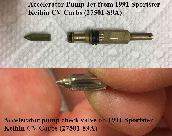
The pump is attached to the Float Bowl. It utilizes a diaphragm bladder & spring that is operated by a rod connected to the throttle cam on the side of the carb. When the throttle is quickly opened, the Idle & Transfer ports are too small to supply enough fuel to keep the carb from starving. To prevent this lean condition, the Accelerator Pump sends fuel thru a supply channel in the bowl body up thru a protruding tube into the venturi. This sprays additional fuel out of its nozzle into the carb air flow to help richen the mixture during the transition off idle (or whenever the throttle is closed & reopened).
There is a check valve utilized to keep the fuel from being pulled from the nozzle tube when the pump rod is released and the AP cavity expands, creating a vacuum. In the 2003-earlier models, the check valve is in the nozzle tube (sold as part of the float bowl). When the pump rod is released, the pump sucks more fuel from the bowl (through a bleed hole in the supply channel) to refill its reservoir and is ready for another transition event.
In the 2004-2006 models, the check valve was moved to the pump body. This required a separate hole in the bowl to allow fuel into the check valve and then to the pump. When the pump rod is activated, the pump output pushes fuel thru the fuel supply channel as it travels to the nozzle tube. A small bleed hole is still utilized in the supply channel but is no longer used to refill the AP reservoir.
  |  |
|||
| Sportster Keihin CV40 Carb | ||||
|---|---|---|---|---|
| Year | Float Bowl | Accl Pump Housing | Float Bowl Seal (O-ring) |
|
| 1988 | 27578-88 | No Accl Pump | 27577-88 | |
| 1989-1990 | 27159-89 | 27160-89 | 27577-88 | |
| 1991 | 27159-89A | 27160-89 | 27577-88 | |
| 1992-2003 - 883/1200 . . . . Except 1200S | 27159-92 | 27160-89 | 27577-92 | |
| 1998-2003 - 1200S | 27380-98 | 27160-89 | 27577-92 | |
| 2004-2006 - 883 | 27777-04 | 27260-00 | 27577-92 | |
| 2004-2006 - 1200 | 27256-01 | 27260-00 | 27577-92 | |

 30) 30) | Float Bowl P/N 27380-98 was used on all 1998-2003 US version 1200S models. These have no overflow tubes. < < < ——————————————— ——————————————— > > > Float Bowl P/N 27256-01, which has an overflow tube, was used on the 2001-2003 International version 1200S models as well as every version 1200 model made from 2004-2006. | 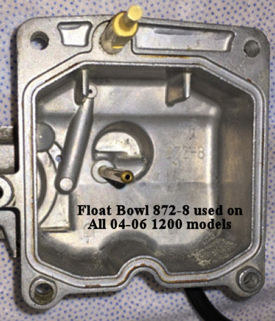 31) 31) |

Fuel Float & Float Bowl Drain


The fuel float is created by a hollow plastic chamber. It moves on a hinge pin mounted to the carb body. It incorporates a TANG (metal tab) that operates the Float Valve. By adjusting the tang in micro-movements, it can raise or lower the fuel level that is maintained in the carb float bowl. See the adjustment specification & procedure earlier in this page.
Fuel Float Hinge Pin - CAUTION! - Be very careful removing the hinge pin on which the fuel float operates. The pin is designed to ONLY be REMOVED in one direction - the direction as shown by an arrow embossed in the carb body. To REINSERT the pin, press it into place in the opposite direction from the embossed arrow. Be careful not to stress or break the mounting posts nor twist & damage the float arms. (Wedge of the XLForum has suggested carefully drilling both posts to barely allow the pin to move freely in the posts since the float bowl, when on, will prevent the pin from escaping the posts.)
Float Bowl Drain - Notice the Drain Tube on the bottom of the float bowl. The same channel that is used to allow the overflow fuel to escape (as a precaution) is also used for a float bowl drain. The drain screw allowed for emptying the bowl of fuel when the carb was being serviced or when the bike was put into storage or unused for an extended period of time. The overflow tube (as shown in previous pictures) was a safeguard against the failure of the float bowl valve from not closing. Should that happen, the fuel would be expelled onto the ground rather than being pushed into the intake manifold and filling the cylinders (and eventually the crankcase) with raw fuel.
Note, however, that the 1998-2003 1200S carbs (US Version) have no overflow drain screw, nor do they have the float bowl overflow tube protection.
Enrichener Function (Choke)
The CV40 has an Enrichener Circuit - It is labeled Choke on the knob, but that is a misnomer, because a choke refers to a plate that restricts the incoming air supply. The enrichener circuit actually provides a path for additional fuel to bypass the carb controls and be injected directly into the air flow at the rear of the carb venturi.
Typically, the enrichener should only be utilized when starting the engine when it is completely cold. Put the enrichener on, let the bike idle for 1-3 minutes, then ride off. Turn the enrichener off as soon as the engine warms up (perhaps within 3-5 miles of riding)…
On a warm or hot engine, you may need to twist the throttle 1/8-1/4 turn to shoot some gas in before starting.
But do not use the enrichener unless the engine will not idle properly.
If the engine won't idle, pull the enrichener knob out enough to get it to idle, ride for a couple minutes and push the knob back in.
Both excess use and insufficient use of the enrichener may cause poor performance, erratic idle, poor fuel economy and fouled plugs.
 The Enrichener Knob is a friction function device. When mounting the knob, do not overtighten the mounting nut. The resistance/friction on the enrichener cable can be adjusted with the knurled nut.
- Loosen the hex nut & remove the cable from its mount.
- Put an adj wrench on the flat part of the cable mounting sleeve.
- Carefully turn the knurled nut to loosen or tighten the tension until the knob stays pulled out on its own yet freely can be pushed back in with reasonable pressure.
- Remount the cable with the lock washer behind the bracket & tighten the metal hex nut carefully (not over-tightening).
Check that the knob moves freely in and out after mounting.
The fuel for the enrichener circuit is drawn thru a fixed jet in the float bowl. The air for the enrichener circuit is taken in thru the banana shaped inlet at the top of the carb face (see the face pic above). Sometimes when the enrichener cable is moved, or the carb has been taken off the manifold, the valve piston does not properly seat into its cavity on the carb. If that happens, additional attention must be given to properly reseating the enrichener valve piston.

An XLForum Thread discussing the replacement of the cable is here (but pics are missing): https://www.xlforum.net/forum/sportster-motorcycle-forum/sportster-motorcycle-intake-and-exhaust/sportster-motorcycle-air-intake-carburetor-efi-fuel-and-exhaust/99252-replacing-the-choke-knob-enrichener-cable-with-pics?t=848307
Reversion - Carb Fog
There is a phenomenon called “reversion” and it's readily identified by a dip in the torque curve (a torque curve is essentially a map of the cylinder fill) and a rich area in the a/f ratio. Sometimes, you also see a fog just outside the carb opening (called a “stand-off”). This situation is not caused by the carb nor can it be fixed by adjusting the carb.
Reversion is created in the engine combustion cycle by the relationship between the cams and the exhaust system. Specifically, between the harmonic waves created in the exhaust pipes and the overlap of the exhaust valve about to close while the intake valve is already opening. This overlap period, where both valves are open at the same time, is usually extended in high lift cams, causing the exhaust system to have a great affect on the cylinder fill operation. The exhaust functioning can have a positive or negative affect.
If/when reversion is occuring, the intake charge ends up passing through the carb three times: pulled in, pushed out, and pulled back in again. Each time it is picking up fuel making the mixture richer. 38)
You can read more in the REF Section on Exhaust Pipes & Cams - Power or Reversion.
More on Jetting
Differences in pilot jets.
See the Charts Here: techtalk:evo:carb01#slow_main_jets_-_p_n_comparisons
& gm1ll t=1553245