Table of Contents

IH: Electrical System
FUSES, RELAYS, CHARGING SYSTEM
See also in the Sportsterpedia:
* 1959-1985 Sportster Illustrated Main Wiring Diagrams (created with reference to the OEM manual)
* The REFerence Section has simplified wiring diagrams for custom rewiring.
* For L84-85 models, be sure to check the warning of a potential danger issue with the main wiring.
Circuit Breakers
Be sure to review the basic Electrical Concepts in the Reference Section, especially wire gauging.
 |
||||
|---|---|---|---|---|
| Circuit Breaker Part Numbers per Year Model | ||||
| Year | Model | Part# | Notes | |
| 1957-1966 | All | X | No circuit breakers were factory installed. | |
| 1967-1968 | XLH | 74589-67 | Circuit breaker with wires. | |
| 1969-E1971 | XLH | 74589-67A | Circuit breaker with wires. Replacement for 1967-1968 XLH | |
| L1971-1972 | XLH | 74589-71 | Circuit breaker with wires. | |
| 1970-1971 | XLCH | 74589-70 | Circuit breaker with wires. | |
| 1972 | XLCH | 74589-72 | Circuit breaker with wires. | |
| E1973 | XLH, XLCH | 74589-73 | (3) “ice cube” 15A breakers. No factory main circuit breaker or fusible wire. TSB #659 directed a fuse wire to be installed. | See Fuse Wire below for more information including placement for different year models |
| L1973-1976 | XLH, XLCH | 74589-73 | (3) “ice cube” 15A breakers. No breaker inline from the battery. Fusible wire installed at factory in circuit. |
|
| E1977 | XLH | 74589-73 | (3) “ice cube” 15A breakers | |
| 74599-77 | 30A “ice cube” main circuit breaker. Breaker shows up on 77 XLH wiring diagram. It's unclear what date the fuse wire was deleted. May or may not have factory main breaker. |
|||
| E1977 | XLCH | 74589-73 | (3) “ice cube” 15A breakers. No breaker inline from the battery. Had factory fuse wire in circuit. |
|
| L1977-1985 | XLH, XLCH XLS, XLX | 74589-73 | (3) “ice cube” 15A breakers. | |
| note: some 77 & 78 → models did not have this breaker | 74599-77 | 30A “ice cube” main circuit breaker. Fuse wire was deleted on some models. |
||
The Circuit Breakers (CB) used on Sportsters are of the self-resetting type. Once they break contact, they will automatically reset after a period of time. These breakers function based on a bi-metallic strip that is heated by current flowing through the strip. More current will cause more heat.
If the rated amperage for the CB is exceeded, the strip will be overheated, causing it to bend away from the internal contact, thereby opening the circuit and removing the current flow. Once the bi-metallic strip has cooled sufficiently, it will return from its heated position and once again make contact. This will allow the current to begin flowing again. If the circuit is still drawing excessive current, the CB will repeat the open & close cycling until the current level is reduced below the current rating and no longer causing the bi-metallic strip to overheat.
Although very reliable, over time & usage, the CB may no longer function at the rated current, requiring replacement of the Circuit Breaker.
The following quotation makes the point that fuses are often slow to react to overcurrent situations. It is critical to replace rated fuses with the same rating in order to properly protect the circuits.
First, fuse ratings can be a bit misleading. A 10A ATO (automotive) fuse will conduct 11 amps for 100 hours minimum. At 13.5 Amps a 10A ATO fuse can take as long as 10 minutes to blow. It is not like once you draw 10 amps “poof” the fuse is gone. (From FUSE SIZING PRIMER located at http://www.powerlet.com/learningCenter/fuseSizing)
Pics of 1967-1972 Circuit Breakers
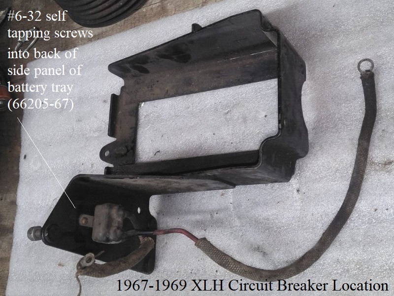
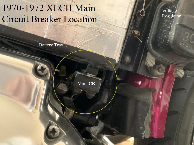
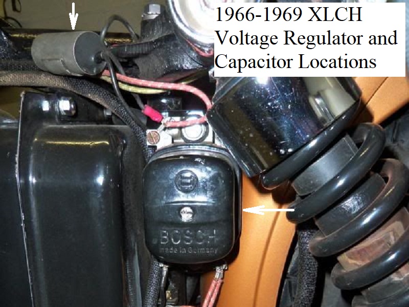
| 1967-1969 Circuit Breaker Location 1) |
 |
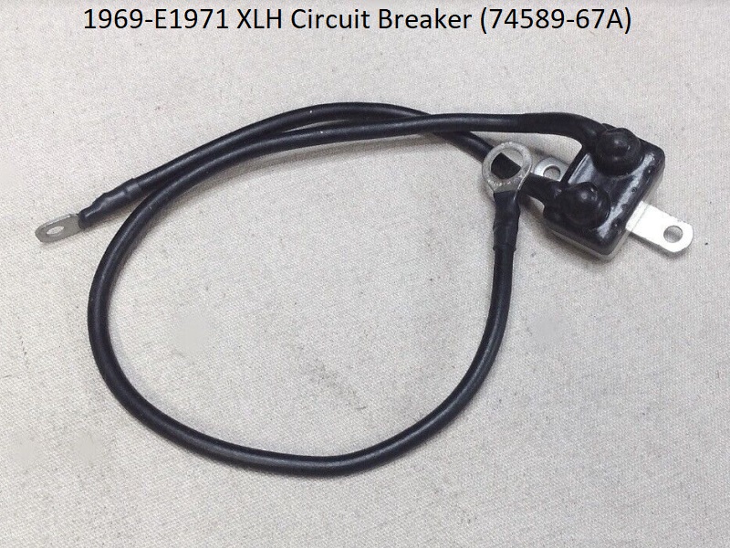
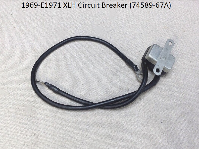
| 1969-E1971 XLH Circuit Breaker with Wires (74589-67A) 2) | |
 |  |
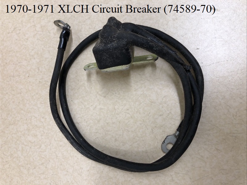
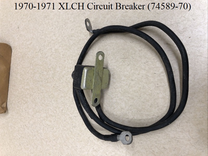
| 1970-1971 XLCH Circuit Breaker with Wires (74589-70) 3) | |
 |  |
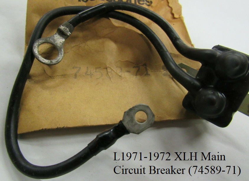
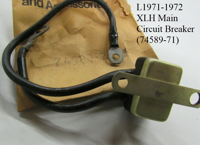
| L1971-1972 XLH Circuit Breaker with Wires (74589-71) 4) | |
 |  |

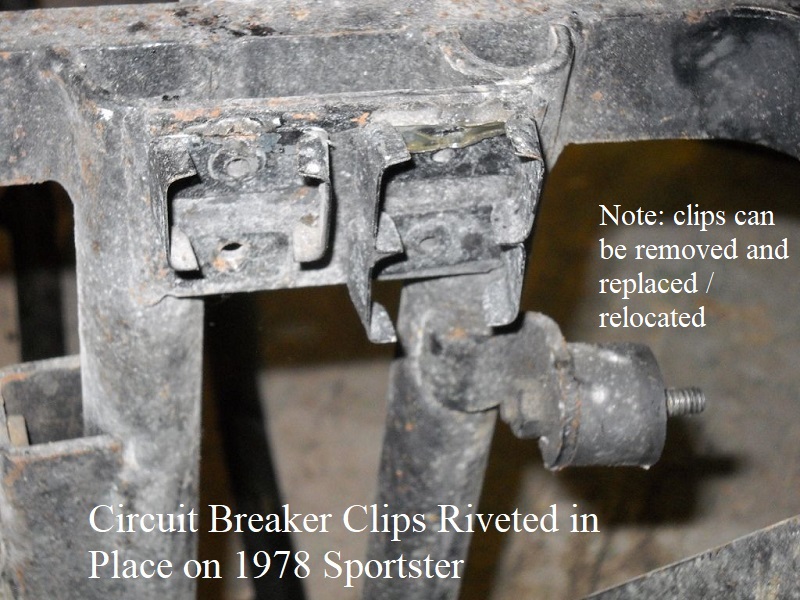
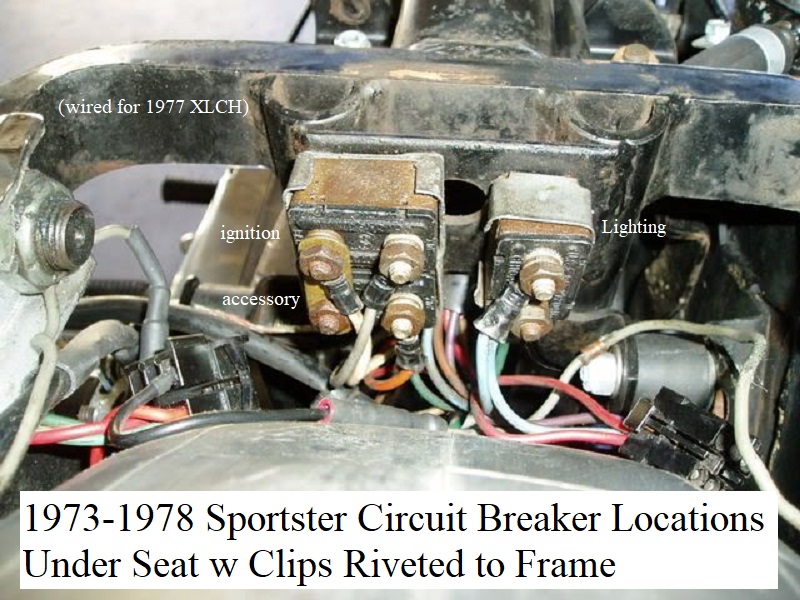
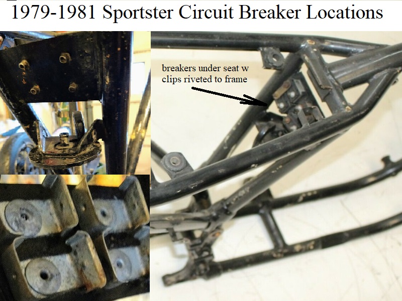
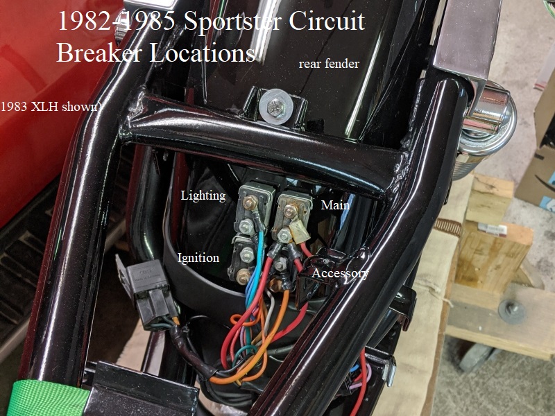
Pics of 1973-1985 Circuit Breakers
Fuse Wire
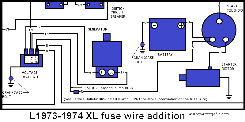
L1973-1974 XL/XLCH:
In late 1973, a 2“ long 20 gauge wire (70105-73) was added in the wiring circuit on FL,FLH, FX, FXE, XL and XLCH models to act as a fuse wire. (TSB #659) 11)
The fuse wire protects the wiring between the battery and the lighting, ignition and accessory circuit breakers.
The theory is that because the motorcycle wiring is heavier gauge, this fuse will burn out first in case of a short or overload and open the circuit.
Caution: Do not use heavier gauge wire for a fuse wire. In place of this HD part, any 20 gauge braided wire will work also.
Before replacing the fuse wire, check for short circuits in the wiring and ignition switch to determine the cause of burnout.
When troubleshooting the electrical system for loss of power, check this wire for burnout at the following locations;
- FL/FLH: The fuse wire is connected to the starter relay terminal (#1) and to the connector in the conduit leading to the battery positive terminal.
- FXE: The fuse wire is connected to the starter solenoid (long) terminal and to the connector in the conduit leading to the starter relay tan wire terminal.
- FX: The fuse wire is connected to the battery positive terminal and to the tan wire connector in the conduit.
The tan wire terminates at the “B” terminal on the ignition switch. - XL: The fuse wire is connected to the regulator “BAT” terminal and to the red wire connector in the conduit leading to the starter solenoid (long) terminal.
- XLCH: The fuse wire is connected to the battery positive terminal and to the red wire connector in conduit leading to the regulator “B+” terminal.
The fuse wire doesn't show up in the -74 FSM schematic but does in the -78 FSM.
Neither the fuse wire nor the connector (#35 in the -78 FSM) for it show up in the parts catalogs or supplement catalogs thru -78B.
But a pic of the wire itself can currently be seen at NOSParts.com https://nosparts.nl/cgi-bin/dbsql/db...umber=70105-73
The pic shows the wire skimmed on each end for connectors.
Looking closer at the wiring diagram, connector #35 also shows up as a splice tap on the green wire coming off the turn signal flasher.
So it appears they simply cut the red wire and used a small crimp connector on it inside the conduit to install the fuse wire inline at the factory.
As to 'connector #35', the FSM wiring diagrams do not distinguish between what type connector they refer to.
It seems they are not referring to a specific part or type but rather denoting a wire splice of sorts.
#35 is designated for the fuse wire, TS flasher, ignition and turn signal lamp wires (some years) etc.
But, going beyond the manual, it has to be small enough to fit inside the wire jacket or conduit without hindering the other wires beside it, especially with the vibration.
Since it doesn't seem to show up in the catalogs specifically for the fuse wire, it could be as simple as a small folded piece of steel.
The TS flasher connector appears to be an permanent 3 way tap as should be the fuse wire with a permanent 2 way.
Permanent meaning a crimp connector instead of a 2 piece socket.
The connectors in the parts books look to range from crimp types to plastic housing punch connectors and simply listed as 'connector'.
If the fuse wire connector could fit in the jacket (like the 75 wire does) then it can't take up much space, as a socket connector would.
Due to positioning, it would need to be a structural sound connection.
The TSB does not require dealers to retrofit this change to previous models.
And a crimp splice is probably what they are referring to in the service bulletin.
Fuse wire placement:

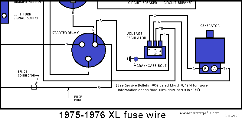
1975-1976 XL/XLCH:
The splice connector for the fuse wire is present in both drawings in the -78 FSM but the word “Fuse Wire” has been omitted on both.
So the fuse wire was also present on 75-76 models. It shows up in the -75 parts books as part number (70057-75)
On the 75-76 XL drawing, the connector is on the wire between the starter solenoid and the starter relay.
Fuse wire placement:
 14)
14)

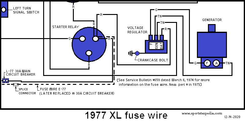
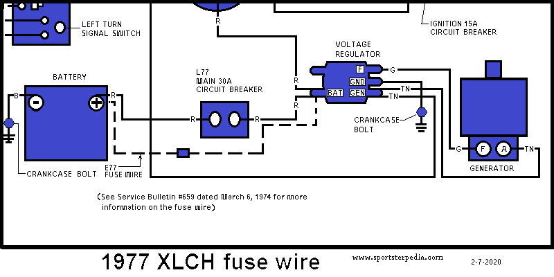
1977 XL/XLCH:
XL:
The fuse wire was replaced with a main circuit breaker in 1977.
Connector #35 is still shown in the wiring key for the splice tap at the turn signal flasher.
The 30 amp (main) breaker (74599-77) doesn't show up in the 77 supplement catalog although it is in the 78 FSM drawing as being installed on 77 models.
It doesn't show up for parts order until the 78 supplement (October 1977 ( 78 year model season)) and even then it shows up for 78 XLH, XLCH (not 77).
The -78B catalog shows it for 78 models as well so E77 models should have come with the fuse wire.
The only reference found to a main circuit breaker being installed on a 77 Sportster at all is the -78 FSM wiring diagram.
Fuse wire placement:
1978 XL:
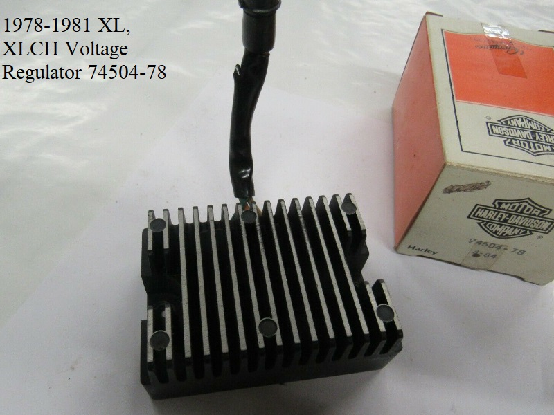
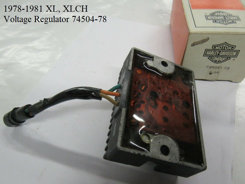
The solid state regulator came out in 78 and the hookup for it changed to a plugged set of wiring.
Yet the 75 fuse wire was being sold for 78 models also so there may be some E78s that came with the fuse wire and older regulator.
Fuse wire placement:

Capacitor
XLCH used a capacitor (32727-63) to improve power to the horn on mid 1963-1969 year models (starting above engine number 63XL 3015) 19)
From 1966-1969, it is mounted on top of the seat casting on the left side bolted with a #10-32 x 5/8“ screw, (3) exterior teeth lockwashers and a nut.
1971 parts catalog shows it's use thru 71 but the L69 wiring diagrams only show the use of the capacitor thru E1969.

Battery
Sub Documents
|
|||||
|---|---|---|---|---|---|
| 1965-1966 XLH | 1967-1978 XLH | 1970-1978 XLCH | 1979-1981 XL/XLCH/XLS | 1982-1985 XL/XLS/XLX |
|
| HD Battery# | 66001-61A | 66006-65 (1) 12v (67) 66006-65A (68-78) | 66006-70 (1) 12v | 65991-75B (79-80) 65991-75C (81) | (65991-82) |
| Voltage | 12v - (2) 6v batteries in series | (1) 12v | (1) 12v | (1) 12v | (1) 12v |
| Yuasa Battery# 22) | 12N7-4A (7 AH) (74 CCA) | YB16-B (19AH) (240 CCA) | AGM (19AH) (270 CCA) |
||
| Motobatt Battery# 23) | MB9U 24) AGM (11AH) (140 CCA) | ||||
Generator
Removal:
There is a trick to removing the generator: Lift up on the inner end and hold down on the outer end then remove it. 25)
Sub Documents
13 Amp Generator 1982 →
- New 13 amp generators were used in 1982 production XLs featuring thrust washers (4 thicknesses to adjust armature endplay from .004“-0.010”) between the rear end cover and rear ball bearing. 26)
- After engine VIN (1HD1CAH1XCY111183) the torque spec was lowered for the armature gear shaft nut at the oil separator washer to 6-8 ft/lbs in order to prevent bowing of the oil separator washer (which can lead to generator noise). Engines exhibiting unusual generator 'whistling' should be checked for this condition. If the washer is found to be deformed it must be replaced. 27)
- This generator can be retrofitted to 1965 models with some guidelines for retrofitting: 28)
- A new voltage regulator (74504-82) must also be used to realize the full 13 amp output.
- A new style drive gear (31073-63A) must be used.
- The internal spline of the old style drive gear will not properly match the spline on the new armature shaft.
- Do not use the new style voltage regulator (74504-82) with a 10 amp generator, component damage can result.
See these XLForum Threads regarding Generator Operation & Testing:
http://xlforum.net/forums/showthread.php?t=39146
http://xlforum.net/forums/showthread.php?t=559976
Polarizing
Polarizing procedure is same for positive or negative ground, 6 or 12 volt.
The purpose of polarizing is to tell the generator whether to output positive or negative ground.
A little bit about polarizing.
Why do generators need to be polarized? Generators need some magnetism to get started. This “residual” magnetism remains in the field pole pieces even after the engine has stopped. The next time the generator starts up, the residual magnetism creates a small voltage in the Armature windings. Not enough to charge the battery, but enough to allow the field windings to draw current. As the field current increases, the pole pieces create even more magnetism. That makes even more voltage in the armature, and the cycle continues until the generator is capable of producing maximum output.
Anytime a generator is disconnected from the system, there is a possibility the residual magnetism may have decreased to the point where it can no longer get the generator started producing voltage. In the case of a new generator or one which has been mis-treated, the residual may even be of the wrong direction (north and south poles reversed).
Polarization is a simple process used to restore the field pole residual magnetism and ensure the magnetic direction is correct.
29)
Diode For Generator Light
A diode is a one way electronic check valve that only allows current to flow in one direction.30) On some Sportsters, a diode is installed in the “Gen” light circuit to help determine if the generator/regulator is working correctly. If all is working the way it should be, with the bike running and everything working correctly, the generator/regulator will be producing a higher voltage than the battery (i.e. it's charging the battery). The voltages at each end of the diode will be such that the diode allows no electricity to flow through the circuit, and the “Gen” light stays off.31)
If your generator/regulator takes a big dump and stops producing the correct voltage, the battery voltage will be higher than the voltage being produced by the generator/regulator. The relationship of the voltages at each end of the diode will then be “reversed” from normal, and that will cause the diode to allow current flow. The “Gen” light will light up, telling you that something is wrong. That's why the “Gen” light lights up when you first turn the key on, as the battery voltage is higher than the voltage being produced by the generator/regulator, since it isn't producing any voltage with the engine not running.
The diode was first shown on the schematics for 1978 models32) and thru Early 1984. Late 1984 & 1985 ironhead models use an alternator instead of a generator, therefore, they have no generator light.
An extensive discussion of the function of the diode is locate in this XLForum Thread.
A simple explanation of the Gen Light is that it is comparing the voltage output from the Generator to the voltage in the system (ie., the Battery voltage). When there is enough difference between those voltages (typically more than 1.5v difference), then the Gen Light will begin to glow. The diode assures that the light will come on only when the Generator voltage is lower than the Battery voltage, meaning the Generator may have a problem.33)
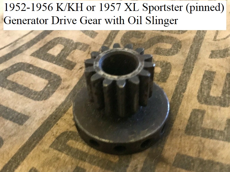
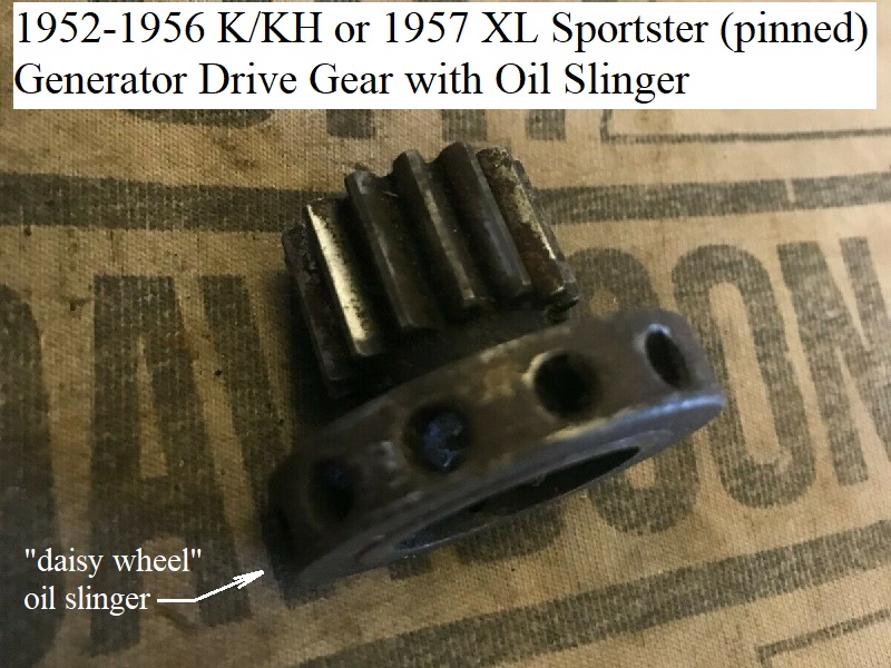
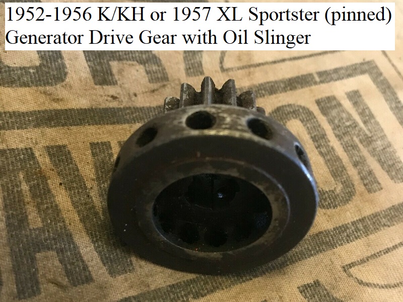
Generator Drive Gears
There were several generator drive gears used for K Models and Sportsters and even more used on other HD models.
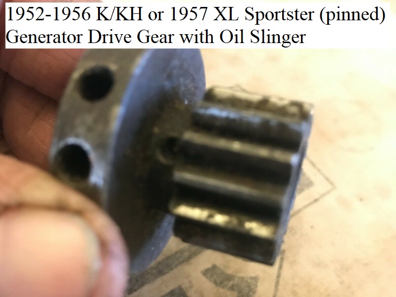
- 1952-1962 K/KH/Sportsters used a drive gear with an integral oil slinger (daisy wheel) on the end and pinned to the generator shaft.
It looks like a gear with a tinker toy connector glued on the end. It's a lathe machined affair combined with a spring loaded sleeve in the cover.
These are great gears but no one repops them and they are expensive and hard to find.- K and KH Models used gear (31071-52).
- 1957 (only) XL Sportster used gear (31071-52A) with no nut or washer.
- 1958-1962 Sportsters also used a daisy wheel gear (31071-58) but now bolted to the generator shaft.
- L1962-1978 Sportsters used a more standard looking 14T gear (31073-63) used with a 1-5/8” washer style slinger (31067-63).
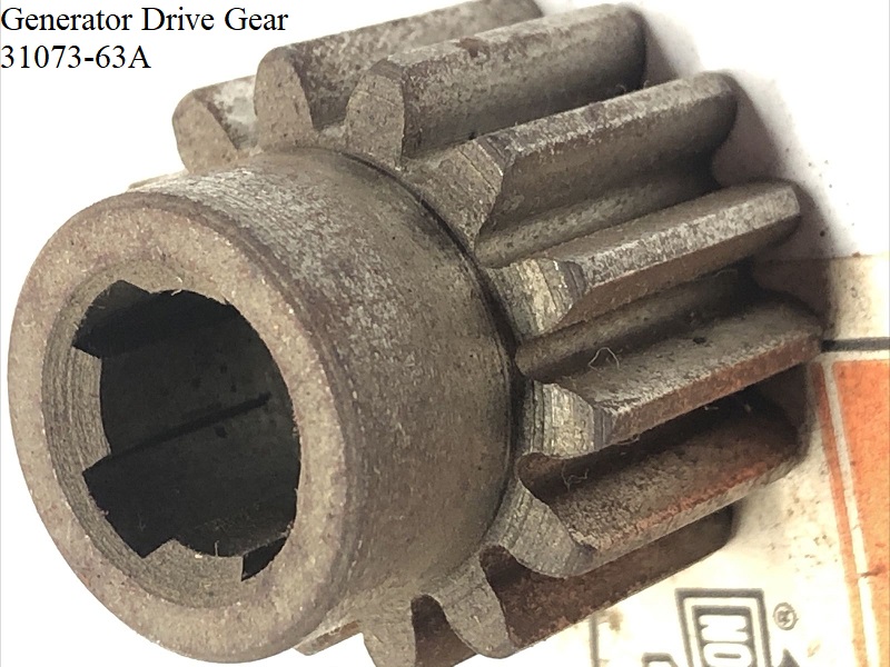
Not as good but a lot cheaper to make. - 1979-1981 Sportsters used 14T gear (31073-63A) with the 1-5/8“ slinger washer (31067-63).
- 1982-E1984 Sportsters used the same 14T gear (31073-63A) with a 1-3/4” slinger washer (31066-82) to accommodate the larger crankcase breather valve.
| 1979-E1984 Generator Drive Gear (31073-63A) 38) | ||
 |  |  |
Starter Relay
The first use of a starter motor on a Sportster was the 1967 XLH. However, it did not come with a relay in the circuit.
The 1968 parts catalog supplement was written in July of 1967 which shows a starter relay “kit” for 1967-E1968.
This suggests that the very early 1968 XLH also did not come with a starter relay but relied on the kit to retrofit the relay.
|
||
|---|---|---|
| Starter Relay Part Numbers per Year Model | ||
| Year Model | Relay Part# | Notes |
| 1967-E1968 XLH | 71455-67 | Relay was part of a kit (71449-67). Kit included the relay, mounting bracket, wiring and hardware. Not all XLH models had the kit /relay installed. |
| L1968-E1971 XLH | X | No factory starter relay mounted. Notably, L68 got a new button switch with heavy wires and a new main cable. 39) |
| L1971-1974 XLH | 71455-67 | Relay was OEM production. |
| 1975-1979 XLH 1979 XLCH | 71463-73 71463-73A | New relay mounted under a new battery tray version configured to hold the relay. (the 1975 parts catalog supplement still shows the -67 relay) It's possible old stock was used up before the new relay was installed. Updated -73A relay sold through -78A parts catalog (April 1981) |
| 1980-1985 XL, XLS, XLX | 31506-79 31506-79A (83) 31506-79B (85) | Small plastic regulator |
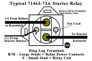
1974-1979 Starter Relay
(1974-1979)
- Starter Relay is auto type, two-bolt frame mount, ring lug for wire mounting
- HD 71463-73A
 40)
40) - NAPA MPE ST404SB
- NAPA ECH ST404

(For 1980-later models, see the Relay section under EVO models).
In some cases, the starter relay used on 1974 to 1979 1200, 1340 and 1000cc models may develop corroded contacts because of moisture under wet road conditions. 41)
Testing
- Using a 12 volt test light, ground one of the leads and touch the other lead to each large relay terminal.
- With ignition switch “on”, one of the terminals should light test lamp.
- When starter button is depressed, the relay should operate and the other large terminal should light the test lamp.
- If lamp does not light, touch test lamp lead to small relay terminal with starter button depressed. If lamp lights, relay is defective and must be replaced. If relay does not light, control circuit from starter button to relay is faulty and must be checked for continuity.
Installation
- Caution, before removing the relay, disconnect the battery.
- Before installing the relay (71463- 73), dip the base of relay in insulating paint or apply with a brush (sealing agent such as GE Glyptal insulating paint) to ensure a good gasket joint seal. This paint (No. 1201 Red Enamel) is available in one quart cans from General Electric distributors.
- The relay is mounted by 2 screws below the battery carrier.
- When reinstalling relay, add two shake proof washers between base plate and battery carrier to provide a good grounding circuit.
- Reconnect the wiring to the relay and the battery and check starter operation.