Table of Contents

IH: Electrical System - Sub-02M
Pics and Information on stock IH Battery Trays and Parts
Below is a short table of battery tray/carrier part numbers by year model.
 |
|||
|---|---|---|---|
| Year | Model | Battery Tray | Notes |
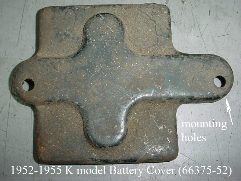
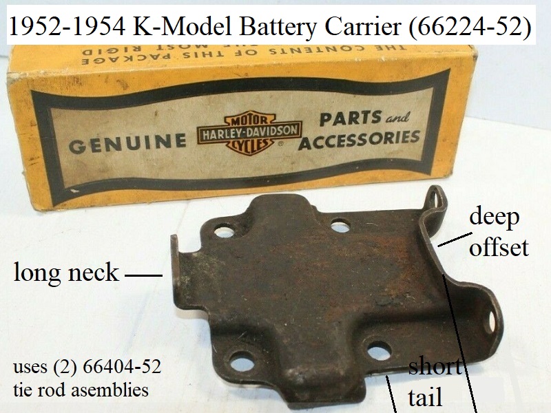
| 1952-1954 | K Models | 66224-52 | battery carrier (1-6v battery) |
| 1955 | K Models | 66224-52A | battery carrier (1-6v battery), replacement for all 1952-1954 K models in 1955 |
| 1956-1960 | KH, XL,XLH | 66224-52B | battery carrier (1-6v battery), replacement for all 1952-1955 K models in 1956 |
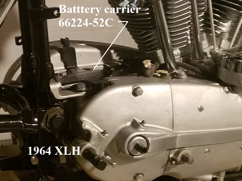
| 1961-1964 | XLH | 66224-52C | battery carrier (1-6v battery), replacement for 1957-1960 models in 1961. |
| 1965-1966 | XLH | 66223-65 | The -65 carrier accommodates (2) 6v batteries for total of 12v. |
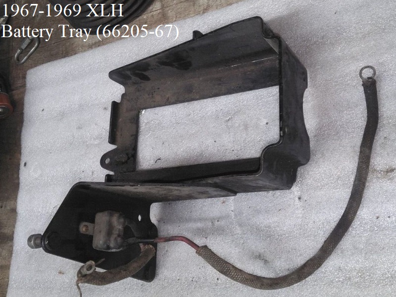
| 1967-1969 | XLH | 66205-67 | 12v battery carrier |
| 1970-1971 | XLH | 66205-67A | |
| 1970-1972 | XLCH | 66208-70 | |
| 1972-1974 | XLH | 66205-67B | |
| 66205-67C (75) | |||
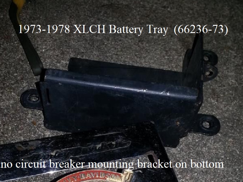
| 1973-1978 | XLCH | 66236-73 | |
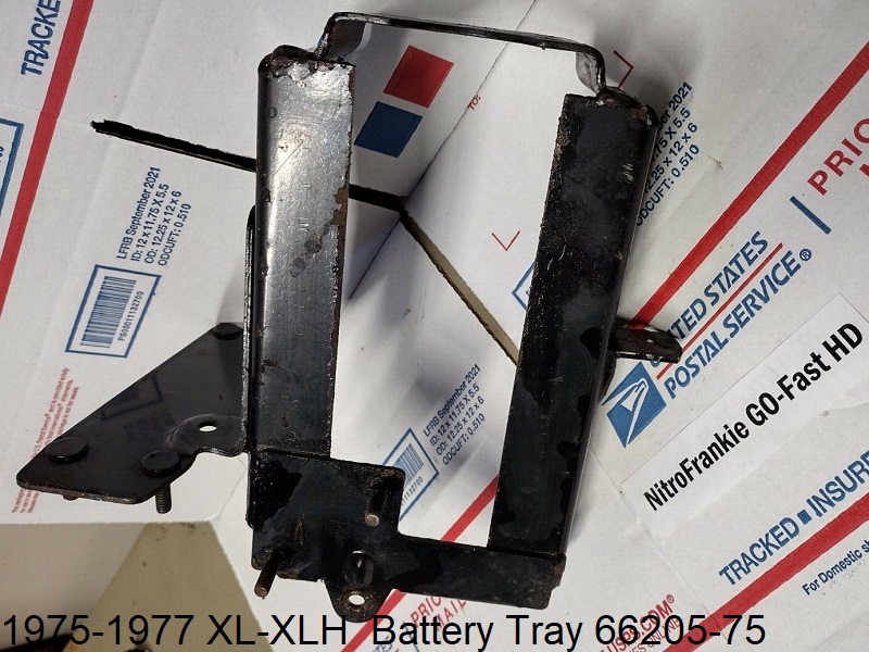
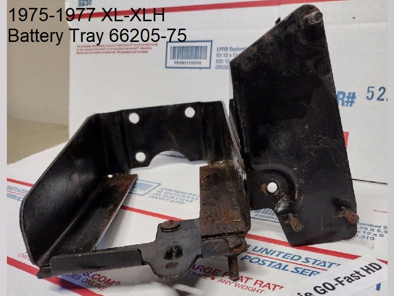
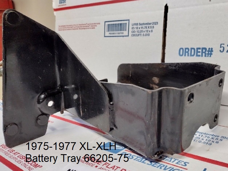
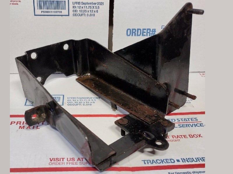
| 1975-1977 | XLH | 66205-75 | |
| 1978 | XLH | 66205-78 | |
| 1977-1978 | XLCR | N/A | Battery carrier built-into oil tank |
| 1979 | XL, XLS, XLCH | ||
| 1980-1981 | XL, XLS | ||
| 1982 | XL, XLS | 66191-81A | |
| 1983-1993 | XL, XLS | 66191-83 | |
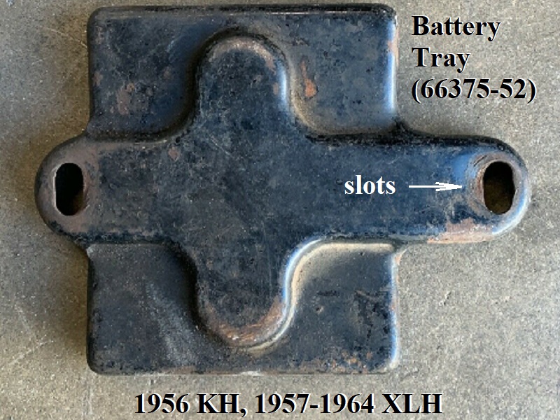
1957-1964 XLH Battery Tray / Parts
Click on a pic to enlarge:
There were 2 different versions of this tray.
66224-52B, for single 6v dry charged battery, uses 6 bolts to mount (all four rear motor mount bolt holes on top of the mount and 2 bolts thru the top of the motor mount to frame).
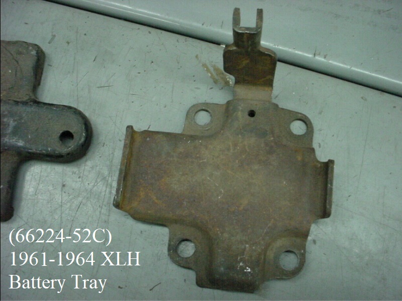
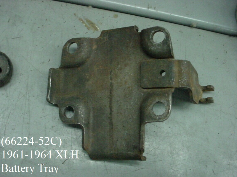
66224-52C, for single 6v dry charged battery, uses only 4 bolts (all four rear motor mount bolt holes on top of the mount).
57-64 XLH battery trays helped support the oil tank where on later models, the battery tray was supported in large by the oil tank.
Click Here for the Oil Tank Lines and Routing page in the Sportsterpedia.
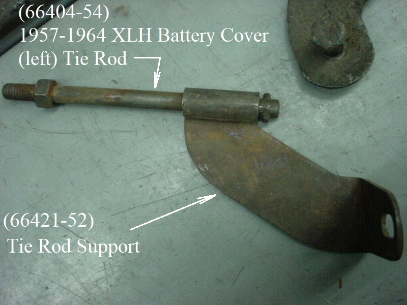
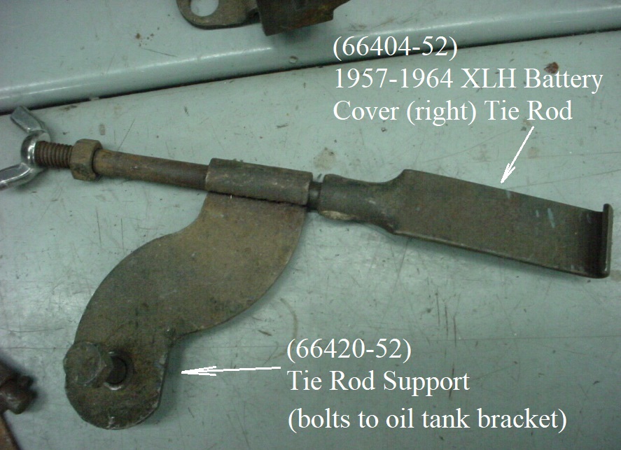
There were 4 different oil tank part number changes from 1957-1964 each of which used the same mounting bracket (47371-52) which accepted the right battery cover tie down support bracket (66420-52).
The left tie rod hooks into the spot welded bracket on the left side of the tray thru a support brace bolted to the tray and secures the left side of the cover.
The right tie rod hooks under the right side of the tray thru a support bracket that bolts to the oil tank bracket (5/16“x24 bolt, lockwasher and hex nut) and secures the right side of the cover.
The cover is bolted to the tie rods with 5/16”x18 wingnuts, washers and lockwashers. The tie rod supports are snugged to the assembly with 5/16“x18 hex nuts.
2 cushion pads (66100-52) are placed 1) under the cover and 2) under the battery for protection.
The K model 66224-52 and 66224-52A battery carriers use the early battery cover with round holes. The 66224-52B and 66224-52C carriers used the later battery cover with slots.
The slots allow the battery to move about 3/8”. The flanges on the -52B and -52C battery carriers moved the battery location rearward, but the tie rods stayed in the same location.
The slotted cover was needed to allow the battery to shift rearward. 3)
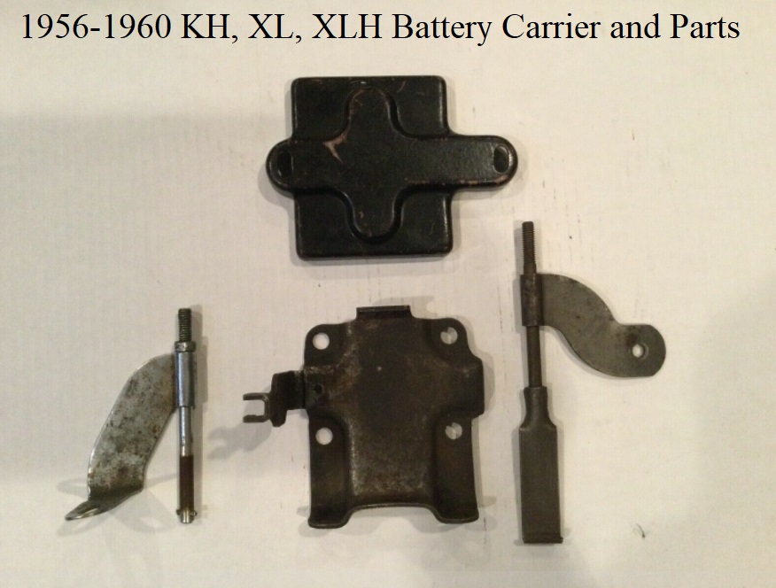
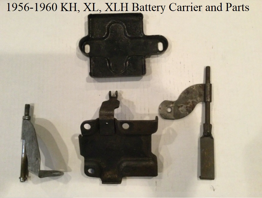
1956-1960 66224-52B
Click on a pic to enlarge:
Below are the OEM parts for 1956-1960:
 6)
6)  7)
7)
Comparing earlier tray versions:
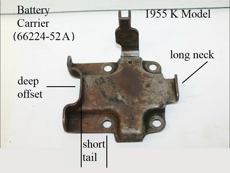
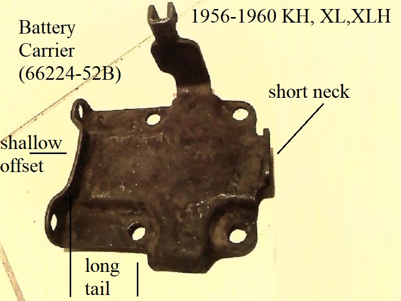
The 1955 K Model tray (66224-52A) looks almost identical to the later -52B version.
But the 1956-1960 tray (66224-52B) has a shorter front neck, more shallow offset at the rear flange and a longer tail section from rear bolt hole to flange. 8)
This shifts the battery more towards the rear than the -52A tray (carrier).
All three of these trays bolt on the same way, flange to the rear motor mount, 4 bolts to the engine case and use the 1952-1960 rear motor mount (16201-52).
The -52 doesn't have the leg support to the oil tank and uses 2- 66404-52 tie rod assemblies. The -52A and -52B both use 1- 66404-52 and 1- 66404-54 tie rod assembly.
The 52-55 carriers leave the battery in a bit more forward position than the 56-60 carrier.
1961-1964 66224-52C
Click on a pic to enlarge:
On the 66224-52C battery carrier, the two mounting holes at the rear flange were removed and the flange sits between the rear mount to frame bolts.
The flange location (and battery position) is similar to the -52B.
The -52C tray is pared with either the 1961-E1962 rear motor mount (16201-58) or the L1962-1966 XLH, L1962-1969 XLCH rear motor mount (16201-58A).
You can see the rearward shift from the -52a tray design easier with the mounting ears no longer on the flange.
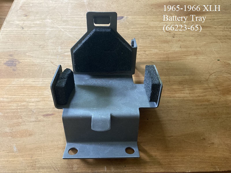
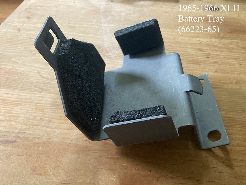
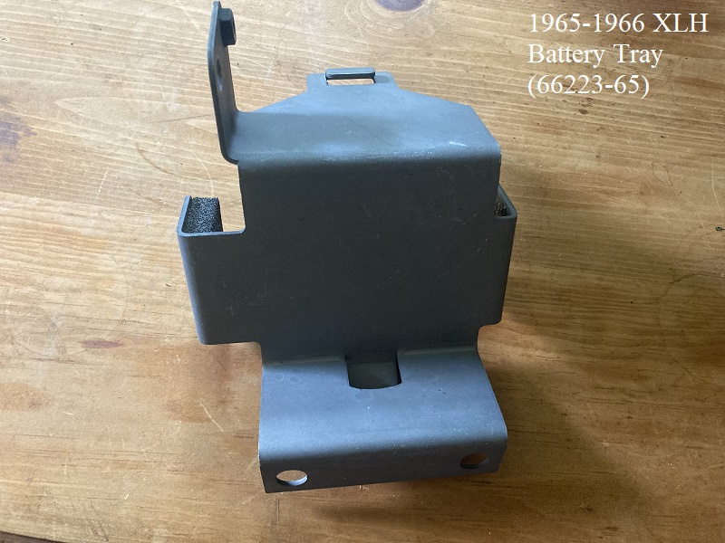
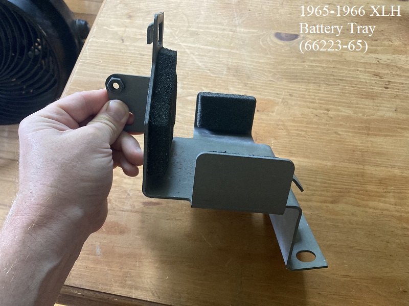
1965-1966 XLH Battery Tray / Parts
1965 marked the first use of a 12v charging system for Sportsters (XLH only). XLCH didn't have a battery until 1970.
The 65-66 battery tray (66223-65) was designed to hold two 6 volt dry charged batteries wired together to create 12v. 15)
The rear of the tray sits on the 4 bolt rear motor mount and mounts with (2) 3/8“x18x1-3/16” bolts (front 2 bolt holes in top of the mount).
There are two sides and a rear wall making up the tray.
The batteries are heavily padded, pad (66418-65) on each side wall, (66101-65) on the rear wall, (66100-65) under both batteries and (66102-65) between the batteries.

1967-1978 XLH Battery Tray / Parts
Mounting the tray
To the Oil Tank:
The battery tray is mounted straight to the oil tank by the 3 holes on the back of the tray with (3) 5/16“-24 x 9/16 hex head screws.
Be careful to use the right length bolts so you don't punch thru the inside of the tank or crack the bracket welds on the tank.
From there, every mounting point (2 for the battery tray and 3 for the oil tank) to the frame/motor has rubber mount isolater studs (62563-65), 5 total. 21)
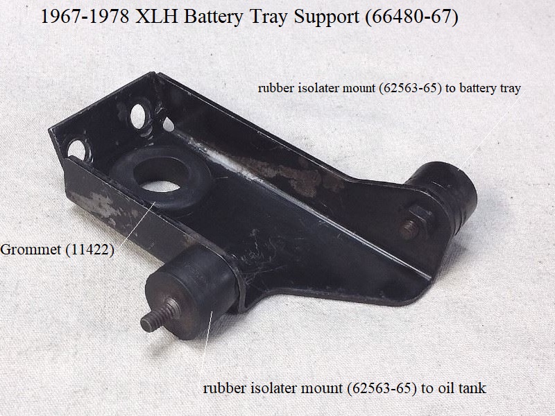
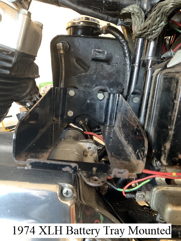
Battery Carrier Support:
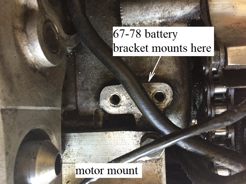
The carrier/tray is lifted off the motor resting on a battery carrier support (66480-67).
The support bracket is mounted to the engine on the 2 holes in front of the rear motor mount with (2) 3/18”x16x3/4“ hex head bolts (4713W) and lockwashers (7038).
The bracket hole in the middle for a grommet (11422) for cable / hose protection.
The battery cable, solenoid to the starter motor, and the 3/8” ID return oil hose to the tank line runs through the hole. 22)
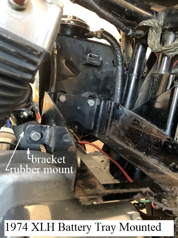
Carrier Front Mount:
The bracket on the left side of the tray gets a rubber mounting isolator stud (62563-65) mounted behind it with 1/4“ lockwasher and 1/4”x20 nut.
The other end of the isolater attaches to the support bracket with 1/4“ lockwasher and 1/4”x20 nut.
Carrier Rear Mount:
There is a terminal block channel welded to the left frame downtube.
On the bottom of the terminal is a threaded 1/4“x20 hole that gets a rubber mounting isolator stud (62563-65) screwed into it.
The 1/4” hole in the tray's side panel sets onto the other end of the isolator stud with a 1/4“ lockwasher and 1/4”x20 nut fastening it to the panel.
Grounding the tray
The battery tray and oil tank are (shock isolated) from the motor and frame by the rubber mount studs.
And most of those rubber mounts retain electrical continuity to/thru both their mounting studs.
If using rubber mounts with the spring inside, the battery carrier is grounded to the frame due to the spring feature in the mounts.
On the inside of the rubber part are two metal plates with the threaded stud attached to each one and then some the plates are connected inside with a spring.
These type rubber mounts ensure electrical continuity from end to end of the studs.
On others, the plates are either glued onto or sunk into the rubber, where the rubber is solid and has no electrical continuity between the studs.
If you're not sure, check for continuity between the two threaded ends with a multimeter before proceeding.
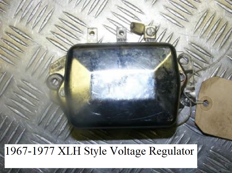
The 3 terminal, 3 coil XLH regulator is mounted over 3 studs on the battery carrier. 25)
The regulator rubber bushes have steel sleeves. The lower 2 regulator bushings have a ground plate that covers the top of the bushes/sleeves.
These ground the regulator to the carrier thru the steel center sleeves.
IT'S ADVISABLE TO VERIFY CONTINUITY WITH A MULTIMETER ESPECIALLY IF USING A NON-STOCK REGULATOR.
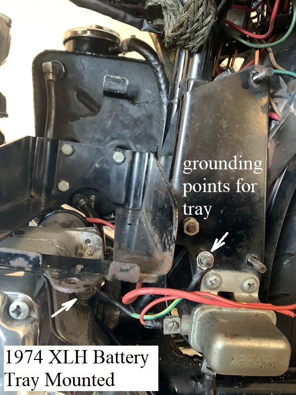
Then depending on year carrier, a ground strap / wire that bolts to the hole under the regulator;
Either goes to the rear starter housing bolt or on the rear (frame) side of the lower rear rubber carrier to frame snubber.
The ground can also be bolted to the regulator / relay mounting studs / bolts. See pics below.
The ground strap was either (70165-58) on 67-69 XLH, (70169-70) on 70-78 XLCH, 70-77 XLH or (70183-78) on 1978 XLs.
The routing and connection points of this wire changed between 74 and 75 models. 26)
1967-E1968 XLH (with the factory relay kit, 71449-67) got a 2nd ground where the support bracket mounts to the front of the battery tray.
There should be a short ground wire making the jump between both ends of the isolator (67-E68). 27)
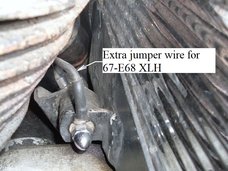
Alternative grounding point for the tray.
Electricals mounted to tray
The battery tray also serves as a mounting point for the voltage regulator, starter relay and main circuit breaker (depending on year model).
Early to late carrier versions incorporate different mounting points for the starter relay and circuit breaker.
The same 3 hole mount voltage regulator (74510-64) was used from 1967-1977.
In 1978, the MoCo installed a 2 hole mount solid state regulator (74504-78).
1967-E1968 XLH models did not have a factory mounted starter relay but had a kit with a mounting bracket to retrofit one.
L1968-E1971 XLH models did not use a starter relay.
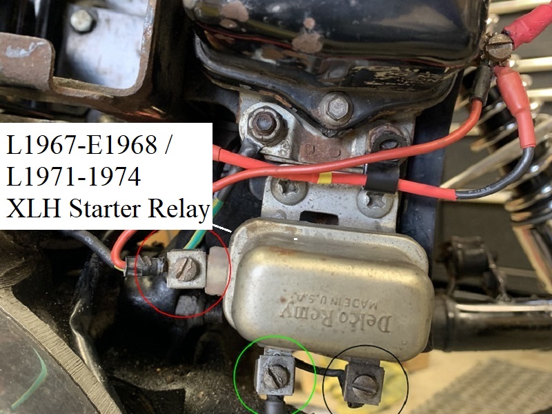
L1971-1974 models mounted the relay (71455-67) on two lower 1/4“ holes on the side panel below the voltage regulator.
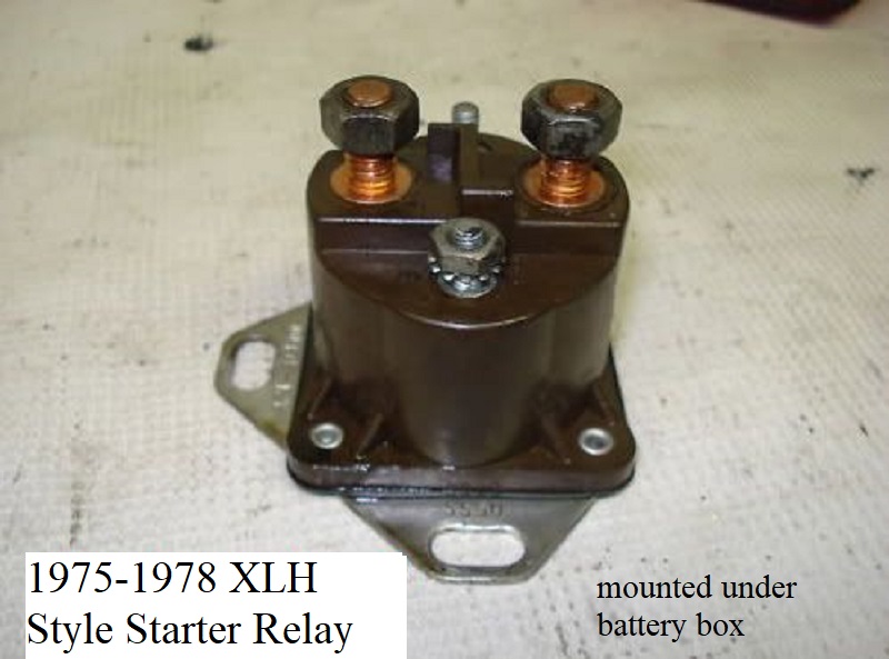
In 1975, a new style starter relay (71463-73A) was mounted under the front right corner of the rear battery tray frame rail.
There is a squared area added to the inside corner of the tray with 2 1/4” mounting studs pointing down for the relay.
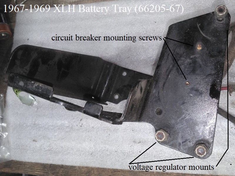
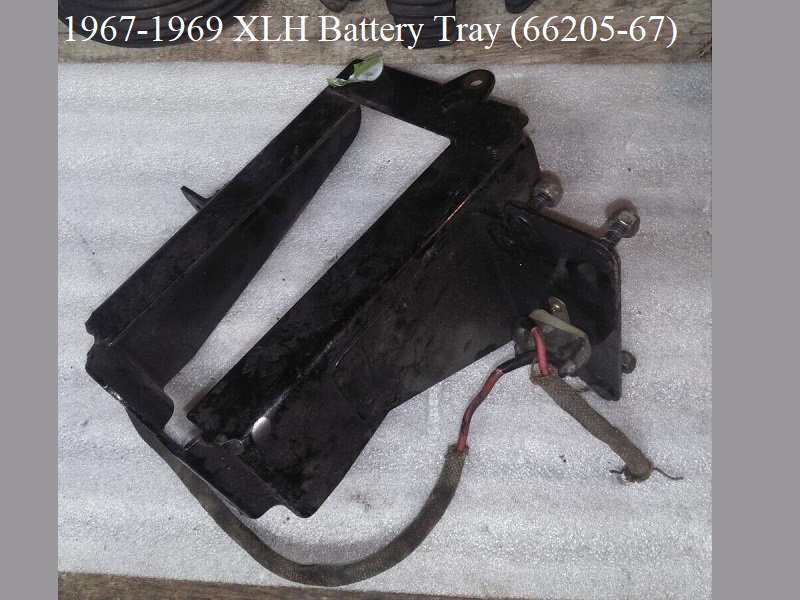
1967-1969 (66205-67)
Features
- Rectangular tray with (3) mounting holes in the rear wall, welded mount on left for a rubber isolator mount.
- Welded on side panel with 3 welded studs in it for mounting the voltage regulator.
- There are no holes below the regulator to mount a starter relay. In fact, the bottom of the side plate isn't long enough to add holes for the relay.
- There are (2) small holes running vertical about center of the side panel for mounting the circuit breaker.
- No terminal block on the edge of the side panel.
More on the terminal plate is discussed below in the 67-69 tray upgrade section.
Used 1967-1969 XLH Battery Tray (66205-67) with the 67-E68 placement of the circuit breaker.
 35)
35)  36)
36)  37)
37)
Attachments
Circuit Breaker
1967-1968 used circuit breaker (74589-67) with wires. 1969 XLH uses circuit breaker (74589-67A) with wires that also replaced the 67-68 breaker.
Either breaker mounts behind the panel opposite the voltage regulator.
1967 XLH circuit breakers used a #6-32 self tapping phillips head screw (2572W) with no drill point on the end.
1968-1969 XLH circuit breakers use a #6-32 hex head self tapping screw (2573W) with no pilot drill point on the end.
Either type screw requires a pilot hole to be drilled first before threading can be done.
2 pilot holes were factory drilled into the side panel of the battery carrier panel (pre-drill size for the tapping screw).
The breaker screws are short enough not to punch into the regulator.
Starter Relay
1967 and some early 1968 XLH models did not come factory with a starter relay.
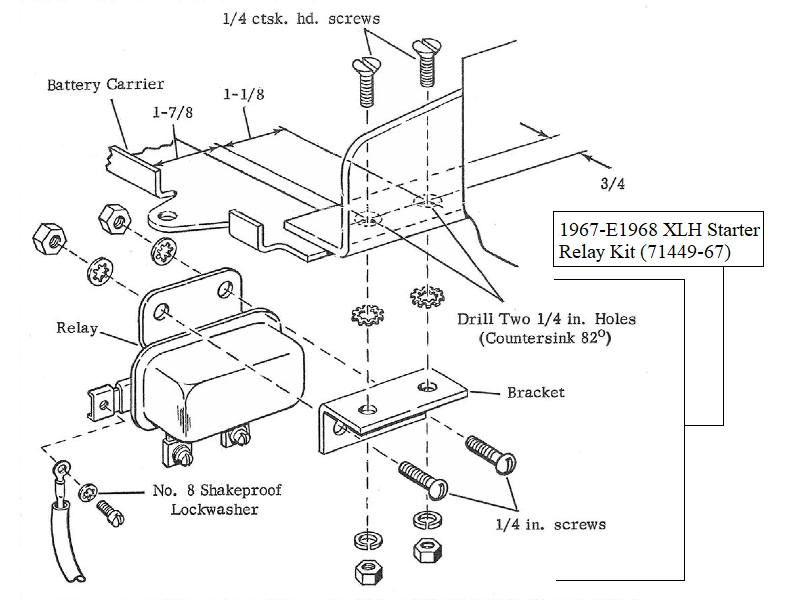
1968 parts catalog supplement (July 1967) lists a STARTER RELAY KIT (71449-67) with relay (71455-67), mounting bracket (71613-67), wiring and hardware.
There are no TSBs discussing the relay or placement for adding one but you can Click Here to find and download the instruction sheet for the kit.
The bracket for the relay is mounted under the rear frame rail of the battery carrier.
Not all XLHs even got the relay installed so a battery tray with/without holes for the relay is of little significance when comparing different period trays.
The 1/4“ holes and placement thereof (if the relay was added) may have been drilled by HD, an Indy or the owner.
Starter Relay Kit (71449-67)
L1968-E1971 XLH models had no factory relay installed.
Assumingly, some time before or after the -68 parts catalog supplement was issued, the starter relay was deleted entirely.
And L1968 XLH> got a new starter button switch with heavy wires and a new main cable. 38)
Tail/Brake Lights and Turn Signals
Base 1967-1969 XLH models did not come factory with turn signals.
Stock tail light assemblies were wired to a 2 point insulating terminal block (71561-67) on the frame.
The terminal block mounts to the left downtube by two attachment points below the regulator mounts.
It serves as the junction point so that the rear fender can be removed. 39)
No wiring terminal provisions are on the -67 battery tray to mount tail/brake or turn lights.
The wiring was a basic twist and shield operation in the rear with wires run up to the terminal board at the forks.
In 1970, the MoCo sold a new style tail light assembly (68010-64B) and also turns (68554-67A) for 1967-1969 XLH.
This where the -67A battery tray came into play for 1967-1969 XLH models, it has terminals for tail/brake and turns.
Updated Battery Trays for 67-69 XLH
All 1970-1977 battery trays were eventually sold as replacement for the original -67 battery tray.
Basically any 1967-1978 battery tray will bolt up to 1967-1969 XLH models. But there may be some considerations to make depending on certain features needed.
The same (3 stud) voltage regulator (74510-64) is used on 1967-1977 XLH models.
The 1978 tray used a different regulator with only 2 studs and will not fit 67-77 regulators. Also there's no provisions to mount a circuit breaker on it.
The list below names some considerations for using 70-77 battery trays.
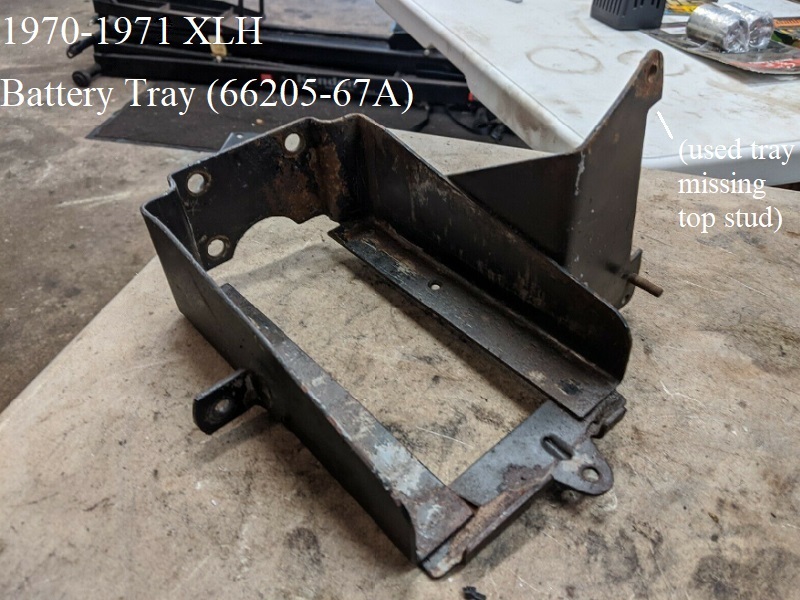
- 1970-1971 battery tray (66205-67A):
- Has a 4 point terminal block built into the edge of the side plate for a junction point for turns and tail/brake lights.
Turns and tail splicing at the terminal block on the panel is done with ring connectors onto plastic expansion nuts. - The side plate was extended down with (2) vertical 1/4” holes to mount the starter relay on 1967-E1968 XLH models.
The starter relay bracket from the relay kit (if previously used) is not needed as the holes replace it. Relay mounts under the regulator.
- 1972-1974 battery tray (-66205-67B):
- Does not have the terminal block feature on the side panel for turn signal wiring.
Will need wiring connectors and clamps/clips if using turn signals. - Does not have the 2 holes on the side panel for the circuit breaker mount on the rear of the panel.
Will need them drilled and tapped if mounting circuit breaker there. - Has 1 countersunk hole under rear frame rail for mounting circuit breaker under the tray.
Uses a #8 countersunk screw thru the top of the rail and a nylock nut on the bottom.
- 1975-1977 battery tray (66205-75):
- Does not have the terminal block feature on the side panel for turn signal wiring.
Will need wiring connectors and clamps/clips if using turn signals. - Does not have the 2 holes on the side panel for the circuit breaker mount on the rear of the panel.
Will need them drilled and tapped if mounting circuit breaker there. - Does not have the countersunk hole under the rear frame rail for mounting circuit breaker under the tray.
Will need a hole drilled and countersunk if mounting circuit breaker there.
- 1978 battery tray (66205-78): Consider another battery tray.
- Redesigned side panel does not accept the three stud regulator.
Panel would need extending and re-drilling to use regulator. - Has the 3 mounting holes to tank in the rear wall and welded mount on left for a rubber isolator mount
- Has squared off area in the corner of the rear frame rail with two studs hanging down for the 1975 style starter relay mount.
- No provisions for mounting circuit breaker.
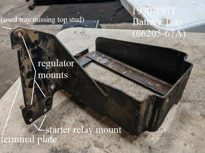
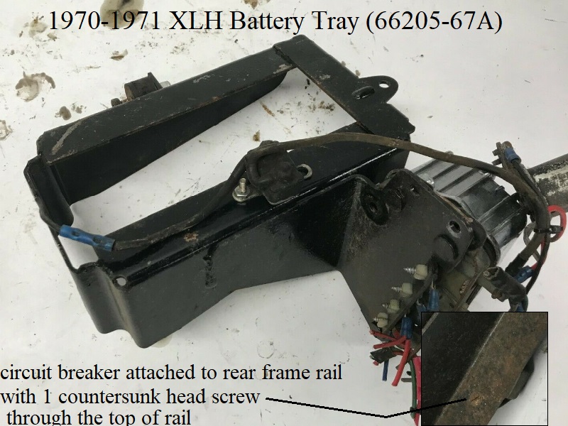
1970-1971 (66205-67A)
This battery tray was designed for 1970 models with features to adapt 1970 style tail/brake and turn assemblies to 1967-1969 XLH models also.
The -70 parts book shows the #6 self tapping screws for the circuit breaker being used on 70 models but with the new -67A battery tray.
And with the -70 book Sept. of 1969, it makes it look like this battery tray could have been a running change from the -67 version.
But that's not very likely since 70-72 frames have a (4 point) terminal strip channel welded to the frame right behind the battery tray panel.
This leaves little room for the circuit breaker in that area.
Features
- Same base frame as 67-69 XLH with (3) mounting holes in the rear wall, welded mount on left for a rubber isolator mount.
- Welded on side panel with 3 studs for mounting the voltage regulator.
- The outside edge of the side panel is cut near the top and pressed back at about 45 degrees by eyesight.
There are 4 square holes cut into this area for plastic expansion nuts.
This terminal block feature was not used on 1970-up models but rather for turn signal and tail/brake light connections on 67-69 models.
1970-1972 XLH models have a (4 point) terminal strip welded to the frame hiding closely behind the battery tray / voltage regulator on the left seat post.
That is where 70-72 tail/brake and turns are connected instead of the terminals on the battery tray.
- Side panel does not have the 2 pilot holes in the side panel for mounting a circuit breaker.
- Has a countersunk hole in the rear frame rail for mounting circuit breaker.
Attachments
Circuit Breaker
1970-E1971 XLH used circuit breaker with wires (74589-67A). L1971 XLH used circuit breaker with wires (74589-71).
-70 parts book still shows the #6 self tapping mounting screws and -71 parts book shows #8-32 countersink screws for 70-71 XLH.
So that may just be a mistake in the -70 parts book.
1970-1971 XLH circuit breakers use a #8-32 x 5/16“ countersunk slotted head screw (1713) and nut (7608) seemingly mounted under the -67A tray.
The -67A battery tray deleted the 2 small circuit breaker holes in the side panel.
The 4 point terminal board on 1970-1977 frames is very close to the rear of the tray side panel.
The -67A battery tray has a countersunk hole drilled in the rear frame rail.
The hole should be there to mount the circuit breaker to the bottom of the frame rail on the battery tray.
With the countersunk screw head inserted into the top of the rail ending flush to the metal, the screw head won't stick up and puncture the bottom of the battery.
Starter Relay
1970-E1971 XLH did not come with a factory mounted starter relay.
L1971 XLH uses starter relay (71455-67), same relay as in the kit for 67-E68 XLH.
It mounts on the 2 lower holes on the side panel under the voltage regulator with (2) 1/4”-20×5/8“ round head screws (2765W) with nuts (7688).
Wiring Terminal Block on the side panel edge
Not used on 1970-up models. The only purpose found for the terminal block feature is for use on 1967-1969 XLH models.
Updated Battery Trays for 70-71 XLH
All 1972-1977 battery trays were eventually sold as replacement for the original -67A battery tray.
Basically any 1970-1978 battery tray will bolt up to 1967-1969 XLH models. But there may be some considerations to make depending on certain features needed.
The list below names some considerations for using 72-77 battery trays.
And of course, a little skill and tools goes a long way in making any of these useable depending on what one has access to or is willing to do.
- 1967-1969 battery tray (66205-67): Not an update for 70-up XLH but will fit with considerations.
- Does not have the terminal block feature on the side panel although it's not needed for 70-up XLH.
- Does not have the countersunk hole under rear frame rail for mounting circuit breaker under the tray (if used).
Will need a hole (or 2) drilled and countersunk if mounting circuit breaker there. - Does not have the 2 holes on the bottom of the side panel for the rectangular starter relay or enough meat to add one (if used).
A bracket will need to be fabbed to install relay. - Has the 3 mounting holes to oil tank in the rear wall and welded mount on left for a rubber isolator mount.
- Has 2 small holes running vertical about center of the side panel for mounting 67-E68 circuit breaker.
Not used anyway on 70-up XLH. - Has the 3 studs on the side panel for mounting the voltage regulator.
- 1972-1974 battery tray (-66205-67B):
- Does not have the terminal block feature on the side panel.
- Has the 3 mounting holes to tank in the rear wall and welded mount on left for a rubber isolator mount.
- Has the countersunk hole under rear frame rail for mounting circuit breaker under the tray (if used).
- Has the 3 studs on the side panel for mounting the voltage regulator.
- 1975-1977 battery tray (66205-75):
- Does not have the terminal block feature on the side panel.
- Does not have the 2 holes on the bottom of the side panel for the rectangular starter relay (if used).
These will have to be drilled if so. - Does not have the countersunk hole under the rear frame rail for mounting circuit breaker under the tray.
Will need a hole (or 2) drilled and countersunk if mounting circuit breaker there. - Has the 3 mounting holes to tank in the rear wall and welded mount on left for a rubber isolator mount
- Has squared off area in the corner of the rear frame rail with two studs hanging down for the 1975 style starter relay mount.
An angle bracket could be fabbed to mount rectangle relay there. - Has the 3 studs on the side panel for mounting the voltage regulator.
- 1978 battery tray (66205-78): Consider another battery tray.
- Redesigned side panel does not accept the three stud regulator.
Panel would need extending and re-drilling to use regulator. - Has the 3 mounting holes to tank in the rear wall and welded mount on left for a rubber isolator mount
- Has squared off area in the corner of the rear frame rail with two studs hanging down for the 1975 style starter relay mount.
- No provisions for mounting circuit breaker.
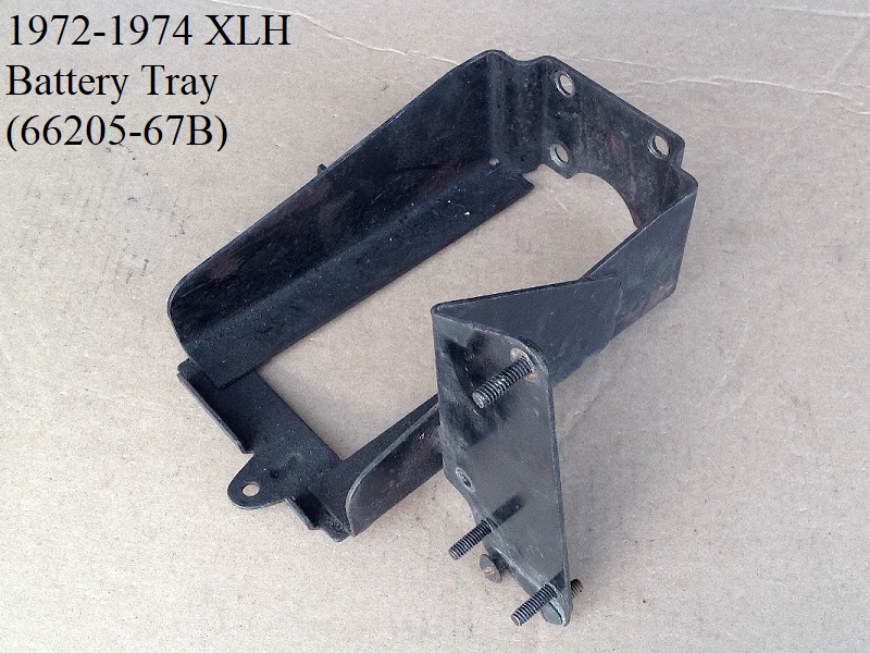
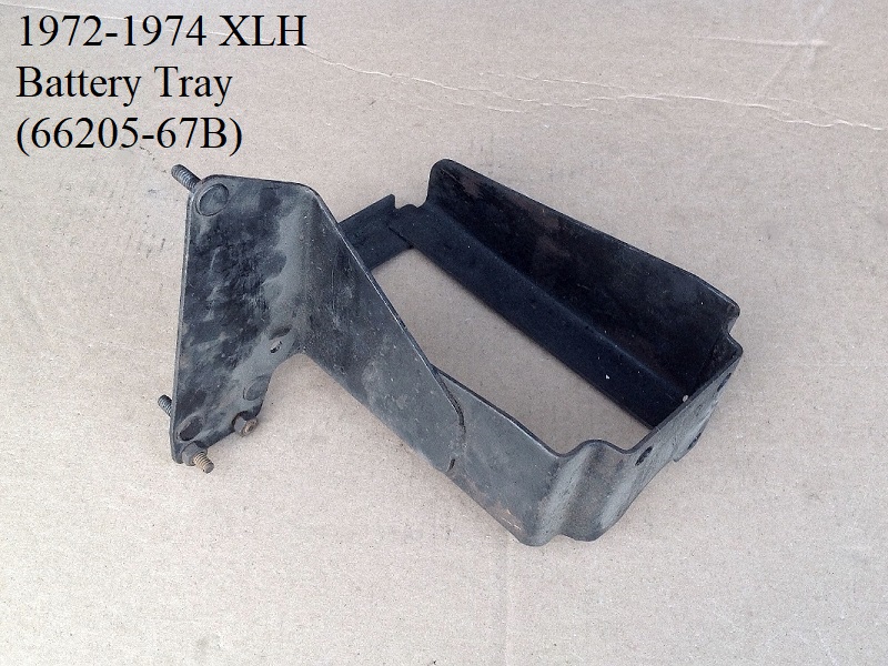
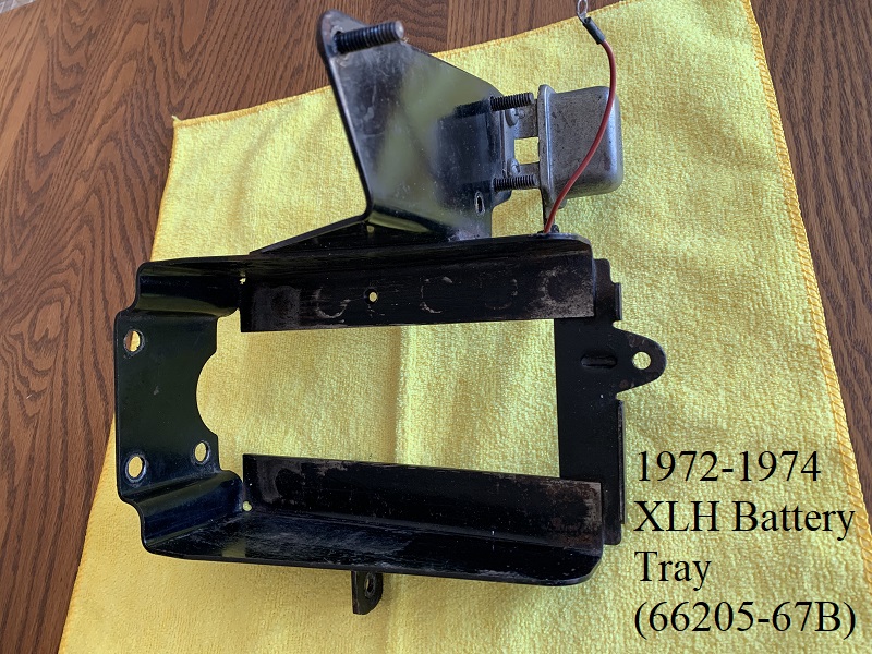
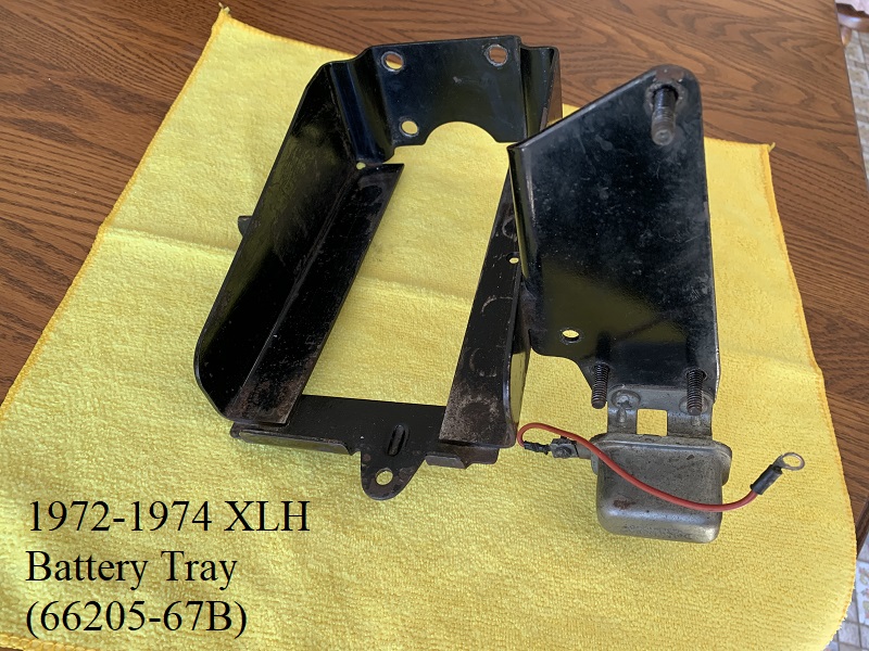
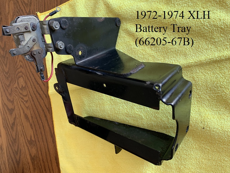
1972-1974 (66205-67B)
The -67B battery tray deleted the terminal plate feature on the regulator plate. Other than that, everything on the tray is the same as the -67A version.
This version was sold for parts order for 67-74 XLH models.
Features
- Same base frame as 67-71 XLH trays with (3) mounting holes in the rear wall, welded mount on left for a rubber isolator mount.
- Welded on side panel with 3 welded studs in it for mounting the voltage regulator.
- Does not have the terminal block feature on the side panel.
- Has the countersunk hole under rear frame rail for mounting rectangular circuit breaker under the tray (if used).
- Side panel does not have the 2 small holes to mount the circuit breaker on rear of panel.
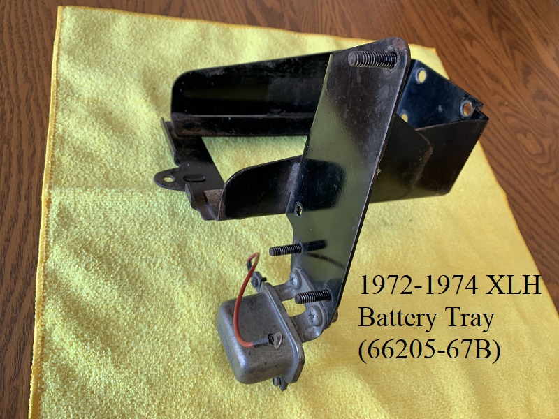
Pics below with correct starter relay (71455-67).
 43)
43)  44)
44)  45)
45)
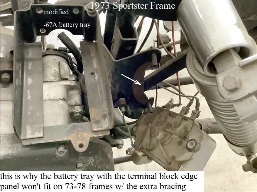
The pic below is a -67A battery tray with the terminal block on the edge panel cut out to fit 1973-up frames with the added strut supports.
The terminal edge is bent backwards which puts that portion into the left strut support.
 49)
49)
Attachments
Circuit Breaker
1972 XLH uses circuit breaker (74589-71) and a #8-32 x 5/16” countersunk head screw (1713) and nut (7608) to mount it.
The battery tray has a countersunk hole drilled in the rear frame rail seemingly to mount the circuit breaker under it.
With the countersunk screw threads underneath the carrier rail, the head won't stick up on top of the frame and puncture the bottom of the battery.
E1973 XLH models were born without a circuit breaker.
L1973-E1978 XLH/XLCH got a fuse wire in the circuit instead of a main breaker in addition to the (3) 15A breakers.
The fuse wire was in different locations for either H or CH models.
Click Here for more detailed information on the fuse wire in the IH electrical section of the Sportsterpedia.
Starter Relay
1972-1974 XLH uses starter relay (71455-67).
It mounts on the 2 lower holes on the side panel under the voltage regulator with (2) 1/4“-20×5/8” round head screws (2765W) with nuts (7688).
1967-1974 Upgrade (66205-67C)
This battery tray was sold for parts order starting in 1975 for use on 67-74 XLH models replacing all previous versions.
1975-1977 (66205-75)
This battery tray was originally sold for 1975-1977 XLH models only.
Features
- Same base frame as 67-74 XLH trays with (3) mounting holes in the rear wall, welded mount on left for a rubber isolator mount.
- Welded on side panel with 3 welded studs in it for mounting the voltage regulator.
- The side panel was moved a little farther to the left of the bike than 67-74 model trays.
To compensate for the distance change the metal area for the rubber mount was pressed / molded rearwards the same distance of the plate shift.
There is a round bossed area in the back of the regulator plate reflecting this change. - Has a squared off area in the corner of the rear frame rail with two studs hanging down for the new -73A starter relay mount.
- Does not have the 2 small holes to mount the circuit breaker on rear of the panel.
- Does not have the terminal block feature on the side panel for turn signal wiring.
- Does not have a countersunk hole in the rear frame rail for the early circuit breaker mount under the battery.
- Does not have the two lower holes on the regulator plate for the early starter relay.
Attachments
Circuit Breaker
There are no factory provisions for mounting a circuit breaker on the -75 battery tray.
L1973-E1978 XLH/XLCH got a fuse wire in the circuit instead of a main breaker in addition to the (3) 15A breakers behind the seat.
The fuse wire was in different locations for either H or CH models.
Click Here for more detailed information on the fuse wire in the IH electrical section of the Sportsterpedia.
Starter Relay
1975-1978 models use the round starter relay (71463-73) which was later updated to (71463-73A).
It mounts underneath the -75 battery tray on the (2) 1/4“ studs hanging down from the cornered bracket in the rear frame rail.
Updated Battery Trays for 75-77 XLH
There are no factory updated battery trays for 75-77 XLH models.
The -75 tray was the last one made for 67-77 XLH models.
It was sold through the -78A parts book for 1967-1977 XLH (replaced those year original trays).
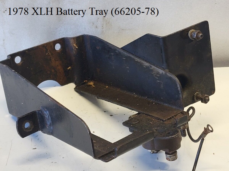
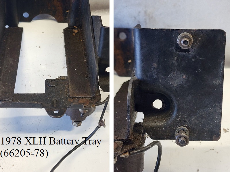
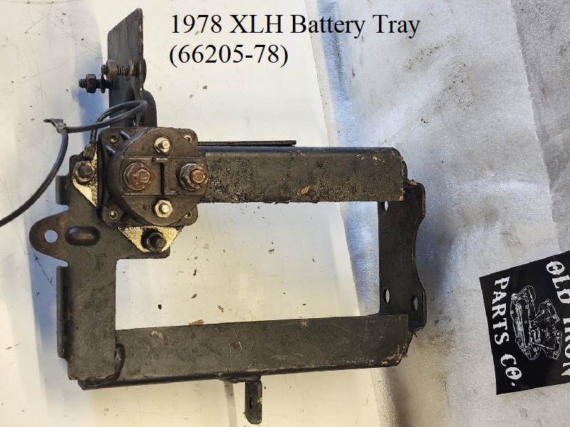
1978 (66205-78)
The 1978 XLH battery tray is basically the same as the 75-77 tray.
However, the side panel is flat across the top and has only 2 mounting studs for the new regulator where 75-77 is slanted to a round point on top with 3 studs.
Features
- Same base frame as 67-77 XLH battery trays with (3) mounting holes in the rear wall and the welded mount on left for a rubber isolator mount.
- Welded on redesigned side panel with 2 welded studs in it for mounting the new solid state voltage regulator.
- The side panel was moved a little farther to the left of the bike than 67-74 model trays.
To compensate for the distance change the metal area for the rubber mount was pressed / molded rearwards the same distance of the plate shift.
There is a round bossed area in the back of the regulator plate reflecting this change. - Has a squared off area in the corner of the rear frame rail with two studs hanging down for the -73 starter relay mount.
- Does not have the 2 small holes to mount the circuit breaker on rear of the panel.
- Does not have the terminal block feature on the side panel for turn signal wiring.
- Does not have a countersunk hole in the rear frame rail for the early circuit breaker mount under the battery.
- Does not have the two lower holes on the regulator plate for the early starter relay.
Attachments
Circuit Breaker
There are no factory provisions for mounting a circuit breaker on the -78 battery tray.
L1973-E1978 XLH/XLCH got a fuse wire in the circuit instead of a main breaker in addition to the (3) 15A breakers behind the seat.
The fuse wire was in different locations for either H or CH models.
Click Here for more detailed information on the fuse wire in the IH electrical section of the Sportsterpedia.
L1978 models used the pop-in style “ice cube” main breaker attached as the other 3 breakers behind the seat.
Voltage Regulator
1978 XLH was factory mounted with a new solid state voltage regulator (74504-78).
The unit is rectangular shaped and the mounts moved in which allowed for the new square top construction on the battery tray side panel.
The regulator mounts to the panel with (2) 1/4”-20 x 5/16“ locknuts.
Starter Relay
1975-1978 models use the round starter relay (71463-73) which was later updated to (71463-73A).
It mounts underneath the -78 battery tray on the (2) 1/4” studs hanging down from the cornered bracket in the rear frame rail.
Updated Battery Trays for 75-77 XLH
There are no factory updated battery trays for 1978 XLH models.
1970-1978 XLCH Battery Tray / Parts
Click on a pic to enlarge:
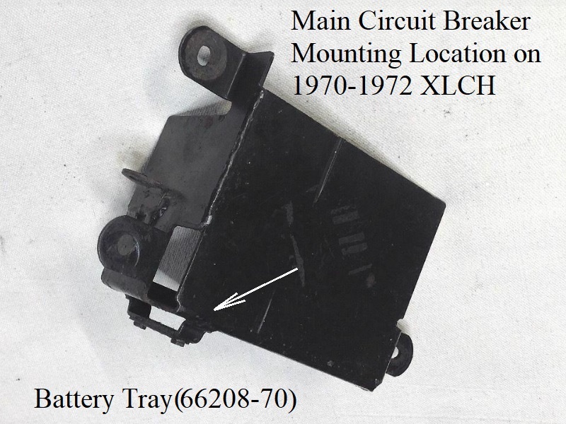
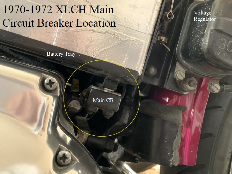
1970 marked the first use of a battery on the XLCH using battery tray (66208-70). There was a main circuit breaker between the battery and the ignition/light switch mounted under the battery tray.
Made for battery (Yuasa model# 12n7-4A) 5.31x3x5.25. 57)
On E1973 models, the MoCo deleted the circuit breaker and in L1973 they added a 20 gauge fuse wire for the main circuit. Click Here to read more about the fuse wire in the Sportsterpedia.
Also Click Here to go to the Service Bulletin page of the Sportsterpedia to download TSB# 659.
The XLCH frame also had dramatic changes in L1973.
The tray is fastened with rubber mounting studs (62563-65) with 1/4“x20 hex nuts on the back and 1/4”x20 acorn nuts (7737W) on the front.
Battery strap (66470-70).
Battery cover came in chrome (66369-70) or black (66371-70).
The pad that the battery sits on is (66100-70) and the cover has 2 pads under it (66352-65) to protect it from the terminals.
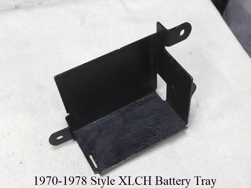
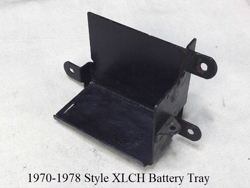
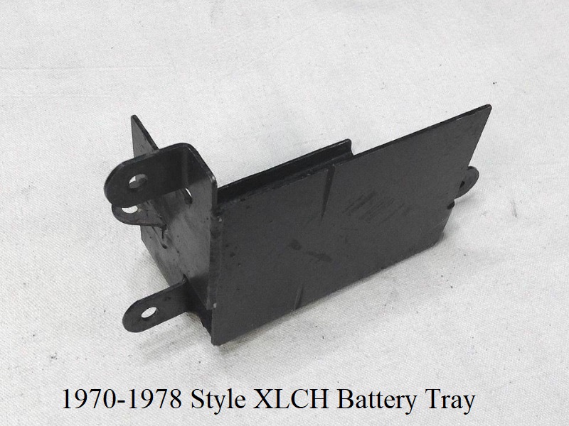
1970-1972 tray (66208-70) has a welded bracket on bottom of tray to mount the main circuit breaker. 1973-1978 (66236-73) does not have that bracket.
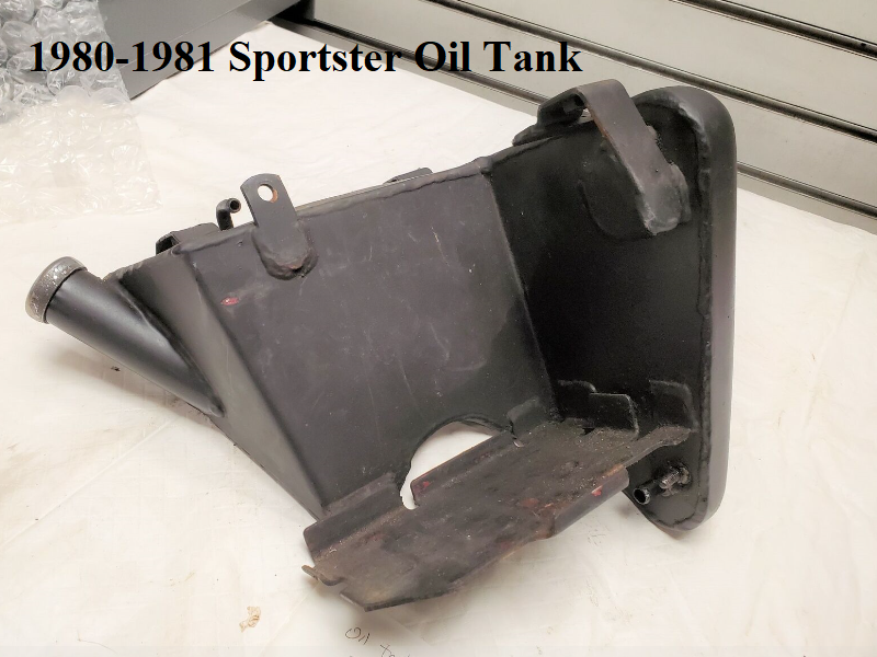
1979-1981 Sportster Battery Tray / Parts
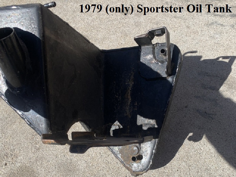
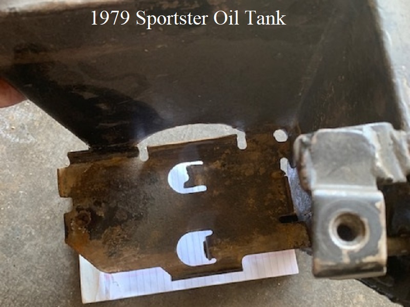
From 1979-1981, Sportster battery trays were built into and are a part of the oil tank.
On 79 tanks, all documentation shows an arm on the left inside wall for one end of a battery strap.
However, finding a used tank that has that strap point can be difficult. It wasn't until 1981 that you could buy a replacement primed oil tank for 1979 models.
Else you had to buy a painted oil tank from the dealer. All documentation on painted tanks do show the battery strap on the wall.
But you can still find used tanks that have the strap arm although you may have to shop around online.
1979 Oil Tank and Battery Tray:
 64)
64)
 65)
65)  66)
66)
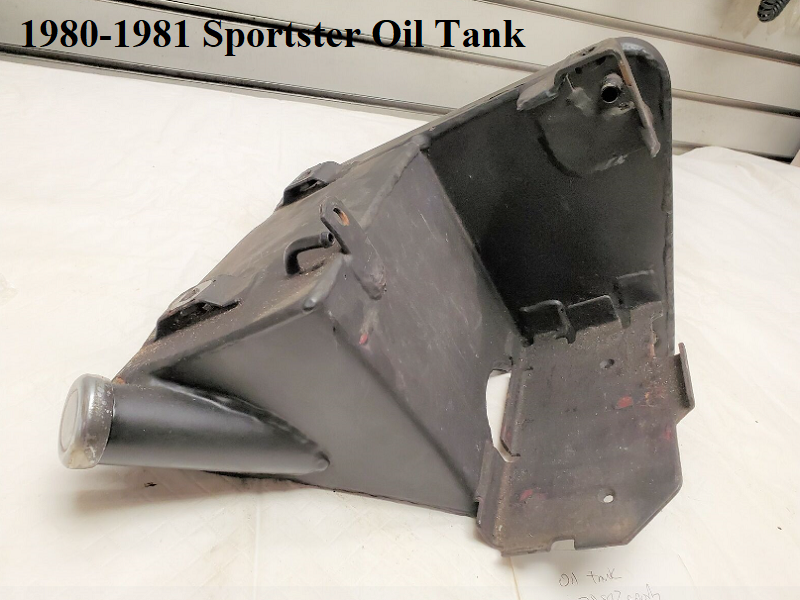
On 1980-1981 oil tanks, there is an extra mounting tab welded to the top inner side of the tank in front of the vent nipple.
An “L” shaped bracket (66279-80) is attached there that is slightly curved on the end with a pad under it as a hold down point for battery.
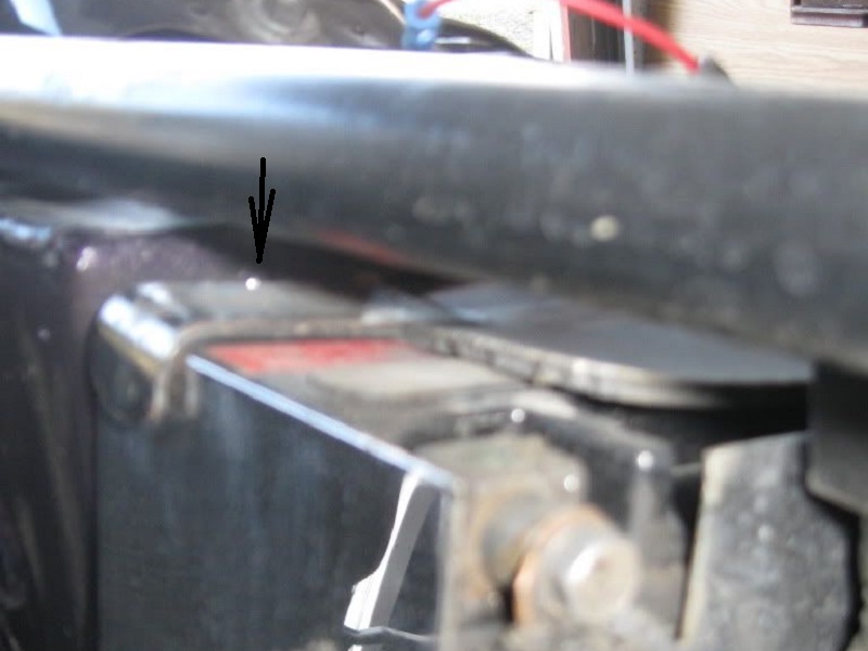
The battery sits on the tray and bracket (66279-80) bolts to the welded tab. There is also a rubber battery strap as in previous.
1980-1981 Oil Tank and Battery Tray:
 67)
67)
 68)
68)
 69)
69)
If this bracket is missing, the battery will need to be strapped and possible shimmed from underneath.
You can try and cut some pieces of rubber or wood trim to shim it until you can purchase the bracket or make one.
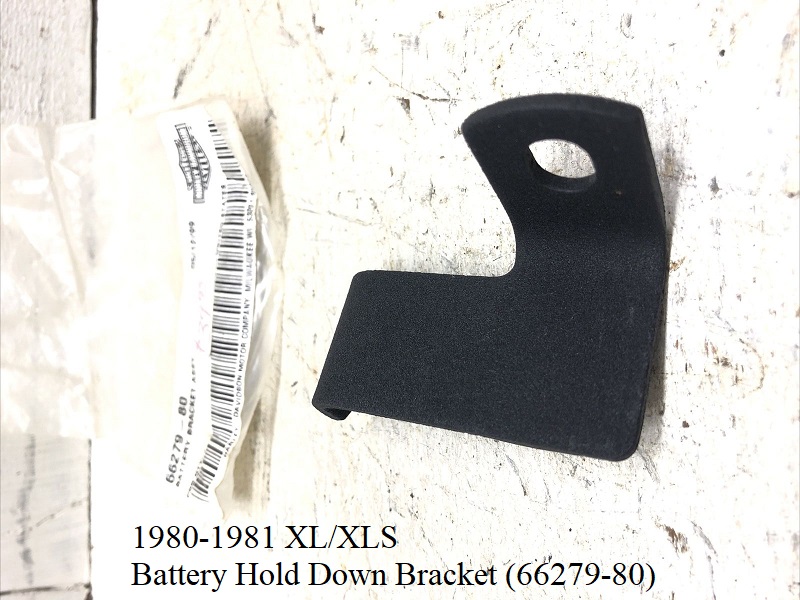
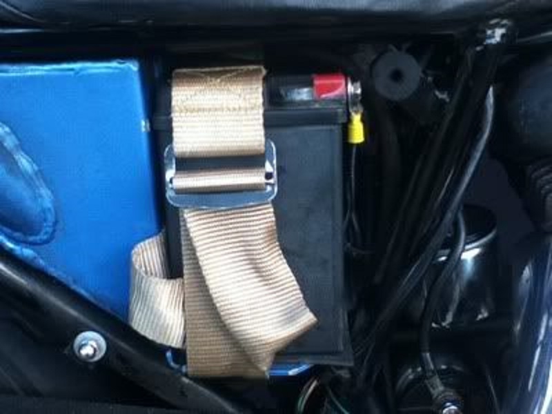
Original Bracket for 80-81 Sportsters installed:
 72)
72)  73)
73)  74)
74)
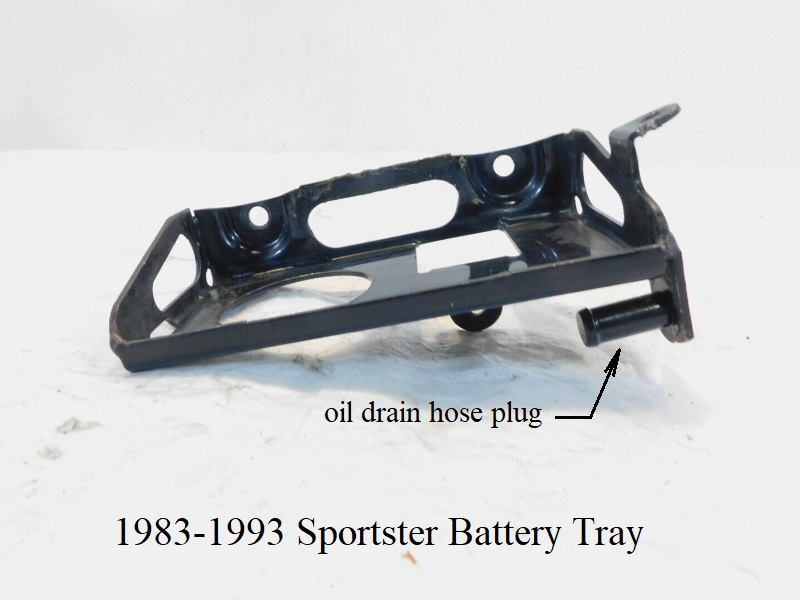
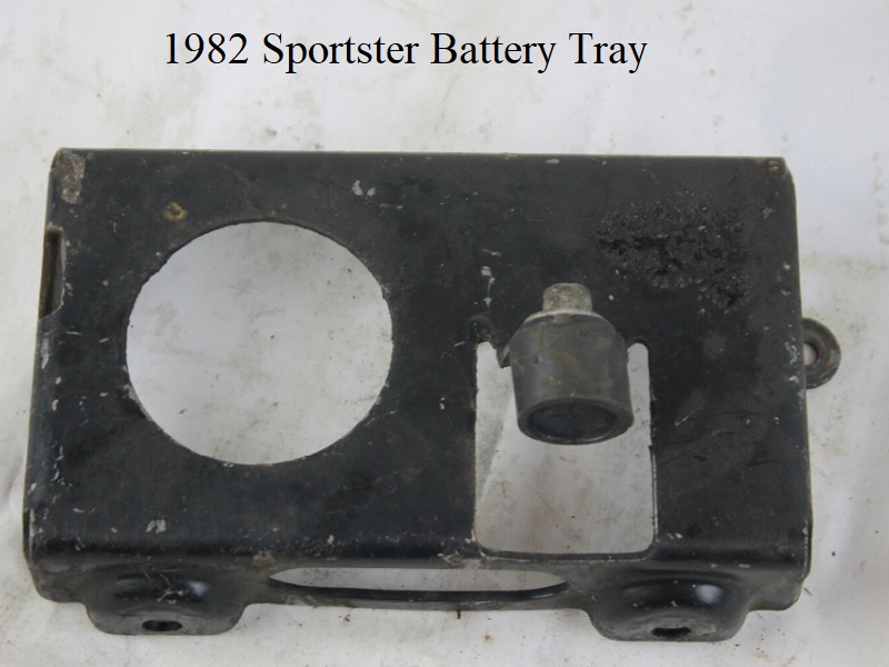
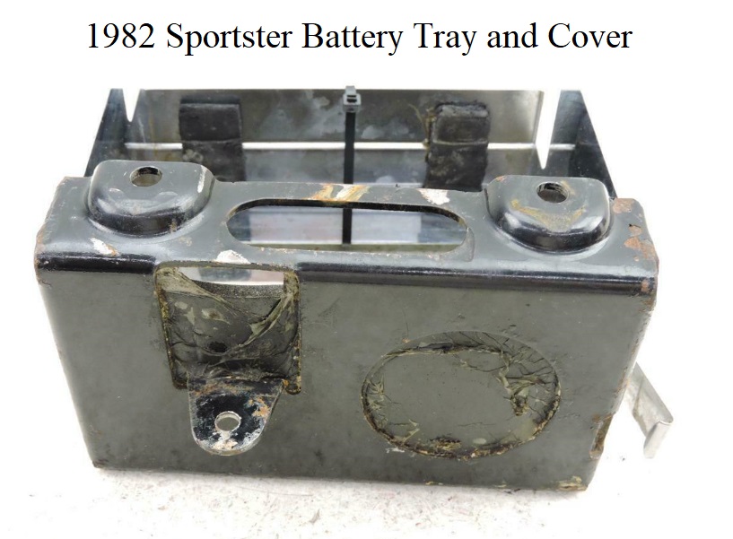
1982-1993 Sportster Battery Trays / Parts
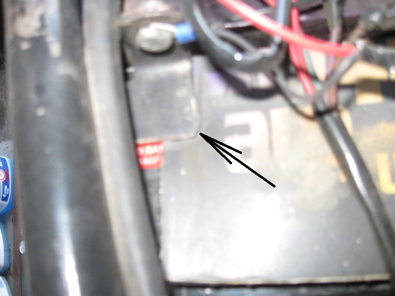
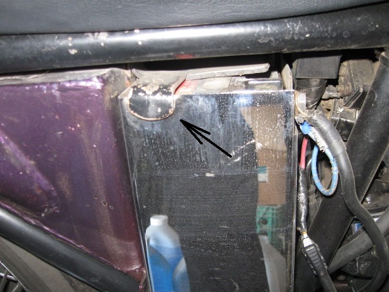
The 82 battery tray looks identical to the 83-93 tray and bolts up the same as well.
However, the MoCo added a flange on the front side extending below the bottom and welded a 1/2“ steel nipple to it as an oil tank drain plug.
The 82-prior oil tanks have a removeable threaded drain plug to drain the tank.
83-up oil tanks have an extra (1/2”) hose nipple on them to drain the tank instead that gets plugged off by the nipple under the battery tray.
The hose runs across the bike from the tank under the battery tray, bends and terminates on the welded plug.
The tray is bolted to the oil tank with two screws in the back and bolted to the frame from underneath with one rubber mount.
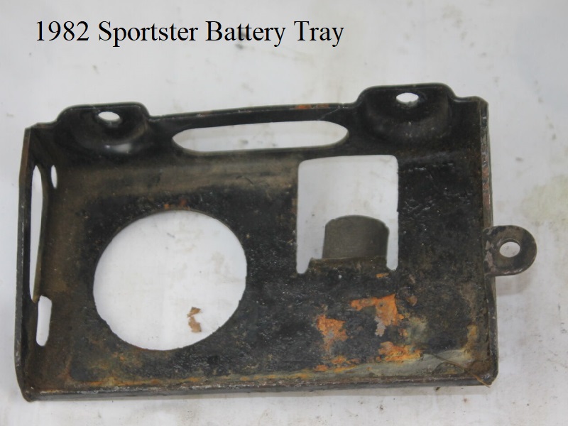
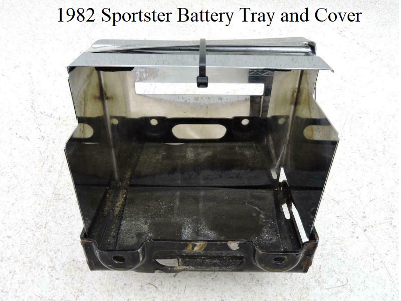
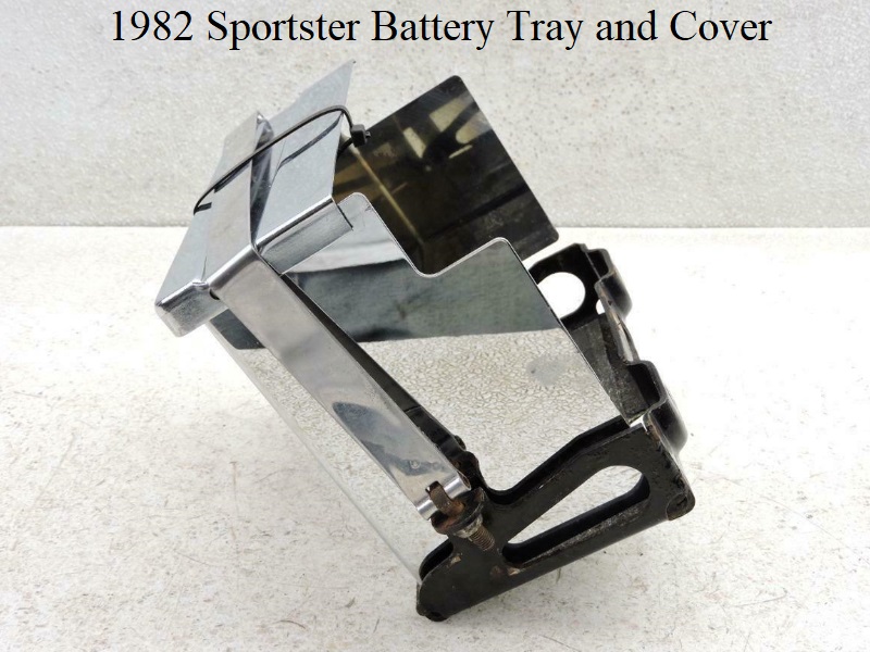
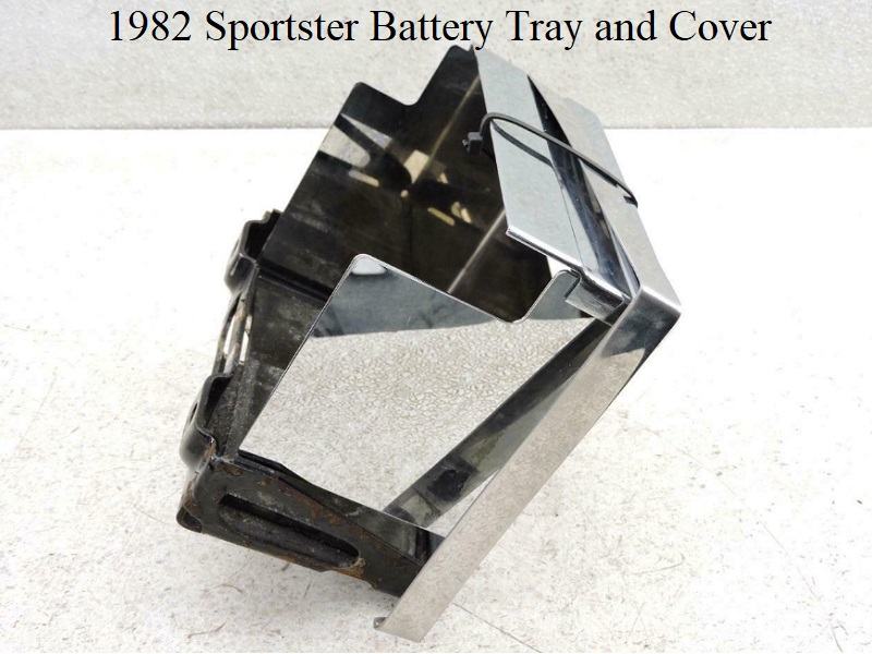
1982 (66191-81A)
Click on a pic to enlarge:
The battery tray mounts to the frame from the bracket underneath with (1) rubber mount stud (62563-65).
It mounts to the oil tank with (2) 5/16“ x 24 x 5/8” hex head bolts with 1/16“ thick washers.
The chrome battery strap (66476-73A) hooks to bottom left side of the tray, loops over the cover (66367-73) and bolts to the right side of the tray.
E1982 used a 1/4” x 20 locknut to secure the strap to the tray while L82 used a 1/4“ x 20 nut and washer.
There are (2) pads (66352-65) under the cover to protect the terminals.
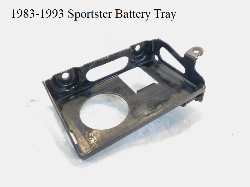
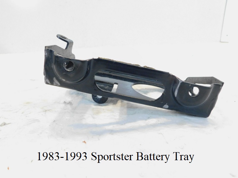
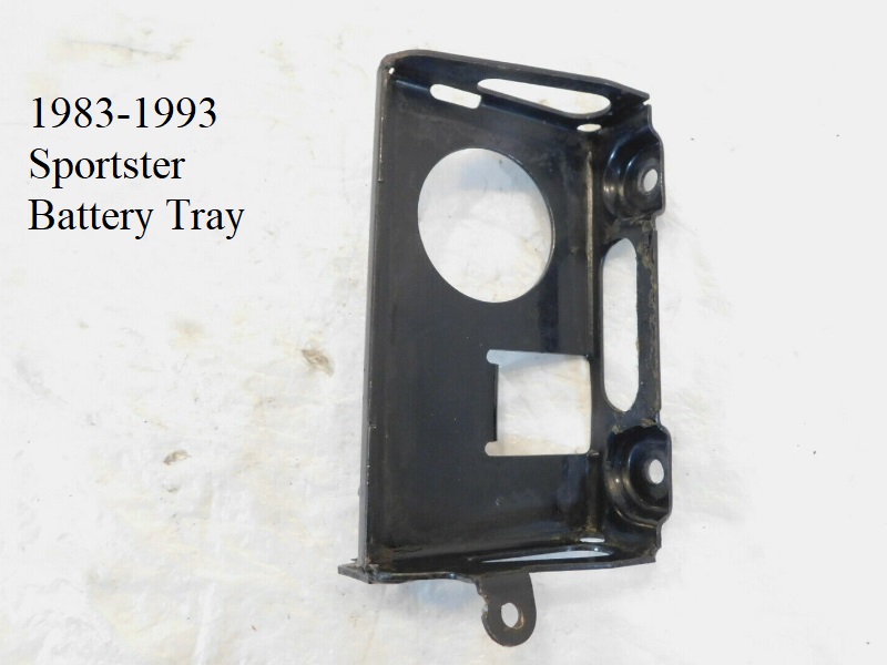
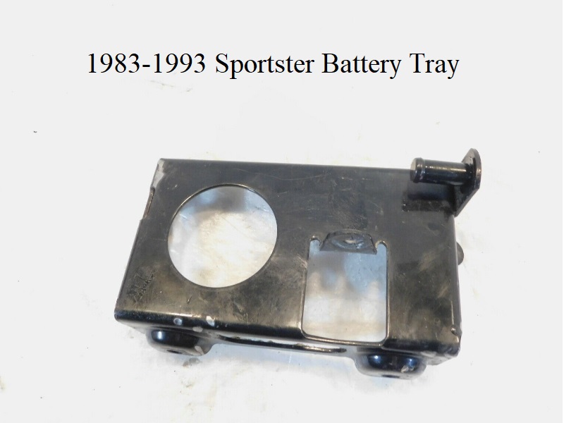
1983-1993 (66191-83)
Click on a pic to enlarge:
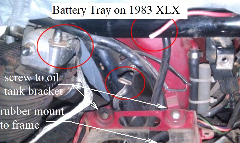
The tray mounts to the frame from the bracket underneath with (1) rubber mount stud (62563-65).
83-90 battery trays mount to the oil tank with (2) 5/16” x 24 x 5/8“ hex head bolts with 1/16” thick washers.
91-93 battery trays mount to the oil tank with (2) 5/16“ x 24 x 3/4” hex head bolts with 1/16“ thick washers.
The chrome battery strap (66476-73A) hooks to bottom left side of the tray, loops over the cover and bolts to the right side of the tray using a 1/4” x 20 nut and washer.
1982-1985 XL, XLS had a chrome battery cover (66367-73).
1983-1985 XLX had a black battery cover (66359-80).
1986-1993 XL883 had a black battery cover (66359-80).
1986-1987 XL1100 had a chrome battery cover (66367-73).
1988-1993 XL1200 had a chrome battery cover (66367-73).
There are (2) pads (66352-65) under the cover to protect the terminals.