Table of Contents
REF: Electrical System
Speedometers
HD Combination Speedo/Tach
HD 70900274 Combination Speedo/Tach
This 4“ Combination Digital Speedometer and Analog Sweep Tachometer is offered as an upgrade item and allows you to monitor engine speed, fuel level and gear position, without adding additional handlebar-mounted gauges. See Fitment Info below. 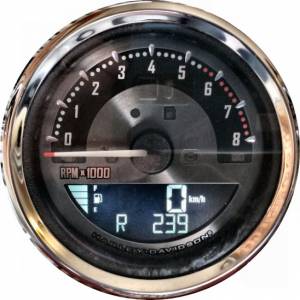 1)
1)
- 4” Spun Aluminum Dial, MPH/km/h, Worldwide Models
- Unit mounts in the stock dash opening and is a direct plug-in installation
- Backlit gauge includes a large LCD (liquid crystal display) information screen that displays odometer/tripmeter data, miles-to-empty readings, an easy-to-read segmented fuel display, a gear position indicator and clock
- Features push-button adjustable backlighting with over 600 color tone options allowing the rider to adjust pointer, LCD and backlighting colors to match any paint scheme or viewing preference
- Digital speed reading can be easily toggled between MPH and kph to simplify cross-border travel
- Mileage reinstatement resides in the vehicle ECM so initial mileage will be uploaded at the time of installation
- 07-later Sportsters require additional Fuel Sensor Kit (HD 61200008A) to utilize Fuel Gauge and Range function
Fitment: Fits '04-'13 XL (except XR, XL50 and '04-'08 XL1200R)
Note: As a result of different vehicle capabilities, the following exceptions apply: Gear position not available on ’04-’07 models, Range function not available on ’04-’06 XL models and ’04-’08 Dyna® models, Fuel level function not available on ’04-’06 XL models.
If you have a 2007-later model, and you choose not to install the 61200008A Fuel Level Sensor Kit, you may use the Speedo/Tach with the stock float sensor to indicate a Low Fuel condition ONLY, rather than installing the multi-level sensor kit. Once installed, set the speedometer fuel tank setting to 'none' to indicate you are NOT using the fuel gauge. Then shut off the keyswitch and remove the MaxiFuse for about 15-minutes. This will cause the speedometer, ECM (& BCM) to reset and discover your preferences.
If this Speedo/Tach is installed on a 2007 model, you must remove the stock 2007 Fuel Sender Resistor Pack (72545-07 - which uses 240/240 ohm resistors) and install the 2008-later version (72545-08 - which uses 8K/2K ohm resistors). 2)
| HD Install Instructions for Speedometer/Tachometer P/N 70900274 can be found here: | ||||||
|---|---|---|---|---|---|---|
| https://serviceinfo.harley-davidson.com/sip/service/document/239891?locale=en_US | ||||||
| Feature List When Adding P/N 70900274 To Various Sportster Model Years | ||||||
| Model Year | Gear Indicator | Trip B | Fuel Level | Range | Clock | Colored Backlighting |
| 2004-2006 | -no- | Yes | -no- | -no- | Yes | Yes |
| 2007 | -no- | Yes | Yes* | Yes* | Yes | Yes |
| 2008-2013 | Yes | Yes | Yes* | Yes* | Yes | Yes |
| * Requires installing Fuel Sensor kit P/N 61200008A | ||||||
HD 70900475 Combination Speedo/Tach
This 4“ Combination Digital Speedometer and Analog Sweep Tachometer allows you to monitor engine speed, fuel level and gear position, without adding additional handlebar-mounted gauges.
Fits 2014-later Sportster models (US). Features are the same as listed above for pre-2014 models.
Requires installation of Fuel Sensor Kit P/N 61200008A to use fuel level and range function.
HD Install Instructions for Speedometer/Tachometer P/N 70900475 can be found here:
https://serviceinfo.harley-davidson.com/sip/service/document/239891?locale=en_US
Koso TNT-01 Speedo/Tach
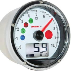 Koso North America - Product: TNT-01 Speedometer/Tachometer Gauge (Discontinued)
Description & Features page is here (SKU: BA035W00-HD):
https://kosonorthamerica.com/product/tnt-01-multifunction-meter-for-harley-davidson-chrome-white
(Available in Black or White Face)
This model is compatible with:
1995-2003 - XL883/1200 - For RPM Signal Source - Can use OEM coil trigger, wrap wire on spark plug cable, connect to CPS (Cam Position Sensor) or from the tach trigger of an aftermarket ignition module.
Installation Instructions are here:
https://kosonorthamerica.com/wp-content/uploads/2020/06/BA035K00-HD-update_v01_comp.pdf
Also Note: There is a generic version of the TNT-01 available that uses a Wheel Speed Sensor for MPH
Koso North America - Product: TNT-01 Speedometer/Tachometer Gauge
Description & Features page is here (SKU: BA035W00):
https://kosonorthamerica.com/product/tnt-01-multifunction-meter-chrome-white
(Available in Black or White Face)
Koso HD-04 Speedo/Tach
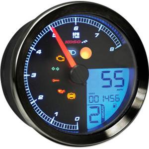 Koso North America - Product: HD-04 Speedometer/Tachometer Gauge
Description & Features page is here (SKU: BA051211 or BA051231):
https://kosonorthamerica.com/product/hd-04-meter-for-harley-davidson-black
(Available in Black or White Face)
Two versions available, both Plug-N-Play:
2004-2013 - XL883/1200 (Uses Serial Data Bus Communications)
2014-later – XL883/1200 (Uses CANbus Communications)
As with OEM meters, this Speedo/Tach requires the 6120008A Fuel Sensor Kit
for the Fuel Gauge Meter to work. See the rest of the options explained in the
Sportsterpedia secton on Low Fuel Sensors.
Installation Instructions are here:
https://kosonorthamerica.com/wp-content/uploads/2020/03/BA051211.pdf
Review by SonWon of the XLForum here: https://www.xlforum.net/forum/sportster-motorcycle-forum/sportster-motorcycle-accessories/200489-koso-hd-01-04-2014?t=2077488
Motogadget Motoscope Mini
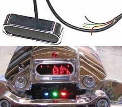 The Motoscope Mini is a compact digital instrument, with 251 ultra bright LEDs for an extremely readable display. It is supplied with a stainless steel speedometer sensor that can be mounted to the front or rear wheel for easy use on various models. It is also compatible with various original speedometer sensors (reed contact and proximity sensors) used by motorcycle manufacturers. An intelligent 'teaching' function provides for easy speedometer calibration - even in cases of vehicles with sensors at the gear box.
Click Here for the Install Manual for the Mini.
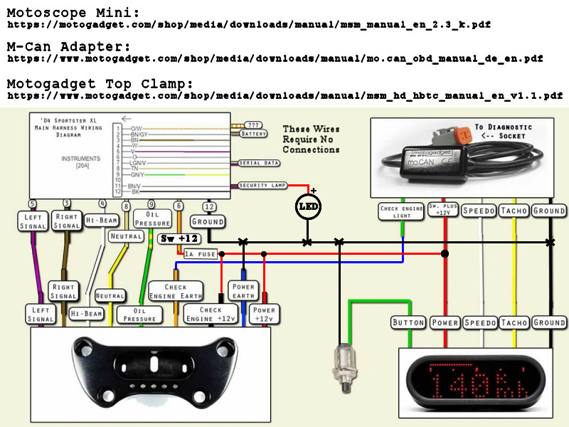
Wiring Functions for the Motoscope Mini Speedo/ODO/Tach3):
| Wire Color | Function & Notes |
| Red | Power Supply - Switched 12v Power (1amp fused) |
| Black | Ground |
| Yellow | Tach Input - From Coil Primary Negative Signal or ICM Tach Output |
| White | VSS Signal or Speed Wheel Sensor (grounding on each revolution) |
| Green | Push Button for Motoscope Mini Control - Button grounds on pressing it |
| Blue | No Function - Not Connected |
The M-CAN OBD is an additional device for use with the Motoscope Mini Speedometer. The OBD will allow you to connect to the Serial Data Link Connector (SDLC) to communicate with the Engine Control Module (ECM). It will allow the ECM to send speedometer & tachometer information to the Motoscope Mini across the Serial Data Bus (SAE J1850 protocol) that is used on 2004 to 2013 models. The M-CAN OBD is not compatible with the later CANbus communication bus on 2014-later models.
The Vehicle Speed Sensor (VSS) from the engine will still be connected to the ECM. The ECM will process the VSS information and provide the necessary communications to the M-CAN OBD over the Serial Data Bus. The VSS may be able to be connected directly to the Motoscope Mini, but the Motogadget instructions for this are unclear or incorrect in some respects.
M-CAN OBD General Information:
https://motogadget.com/shop/en/m-can-signalkonverter-fur-hd.html
M-CAN OBD Installation Manual:
https://motogadget.com/shop/media/downloads/manual/mo.can_obd_manual_de_en.pdf
VSS Compatibility List:
https://motogadget.com/shop/media/downloads/allgemein/s_compatibility_speedo_sensors_01.pdf
(It appears that only 12v sensors are compatible. Not the 5v versions)
Here is a proposed wiring diagram from Post# xx of this XLFORUM Thread:
Fuel Level Sensors Explained
Here is an explanation for the functioning of the Low Fuel Level sensors related to 2007-later models:4)
All the speedo & tachs with low fuel lamps or fuel gauges have an internal voltage level that is sent out to the sensors. That voltage level is monitored by the speedo to see how the sensor unit affects that voltage. Based on how the sensor affects that voltage, the speedo interprets those varied voltage levels as various fuel levels. (The voltage is nominally 12v supplied thru a pull-up resistor and the sensor creates a voltage divider - fixed or variable.)
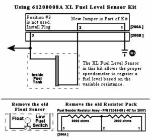
STOCK FUEL LEVEL SENSOR - Idiot Light for a fixed Low Fuel Indication. The stock low fuel level sensor is a float-operated switch. When the float goes low enough, it causes the switch to close. With NOT-LOW fuel level, the Fuel Resistor Pack has a high resistance, keeping the voltage level high. When a LOW-FUEL condition happens, the switch closes and shorts across part of the Fuel Resistor Pack and make the voltage level go lower.
This change of voltage is seen by the speedo and it puts the Low Fuel Light ON. Once sufficient fuel is added to the tank, the float rises and the switch opens, allowing the voltage to also rise, and the speedo sees this and turns OFF the Low Fuel Light.
REPLACEMENT FUEL LEVEL SENSOR - Multiple LED display for a variable Fuel Level Indication. The replacement Speedo/Tach (or other multi-level gauge) requires a more sophisticated sensor in order to provide various fuel levels.
These gauges still provide a voltage to the new sensor & monitors the voltage level to determine fuel levels. This is accomplished with a sensor that is Capacitively Sensitive. When fuel is on the sensor, the resistance is low. As the fuel gets lower, the sensor resistance goes up (because less of the sensor has fuel on it). With these sensors, the Fuel Resistor Pack is replaced by a simple jumper plug, allowing the Capacitive Sensitive Sensor to control the voltage. (The present sensor used in either kit is part number 61200040.)
Based on the low voltage when the tank is full, the speedo lights the most (higher) fuel level bars. As fuel is consumed, and less fuel is on the sensor, the resistance goes up and the voltage goes up. The speedo will reduce the number of bars that are lighted as the voltage goes up. When the tank is empty, the resistance is highest (as well as the voltage) and there will be no fuel bars showing, but the low fuel light will be lit.
As you might have noticed, the capacitive sensitive sensors work exactly opposite of the stock sensors as far as resistance and voltage levels representing fuel levels. This is why it is important to reset the control system (by pulling the MaxiFuse for a minute) after the new sensors are installed.
See below, the special actions needed, regarding the use of the 75031-09 or 75338-09 Fuel Gauge Kit on 2007 models (these mount on the brake master cylinder cover).
HD 61200008A XL Fuel Level Sensor Kit
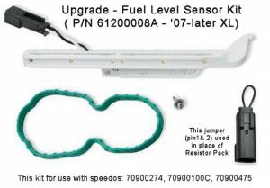
This kit has a graduated, in-tank sensor unit which is based on capacitive sensitive technology to accurately monitor the fuel level. Included is a jumper plug to replace the stock resistor pack and a new fuel pump gasket. Specified to be compatible with 70900100C, 70900274 and 70900475, it has been discovered that this kit will also enable operation of the fuel level gauge on the 2016-later 1200CX Roadster speedometer, P/N 70900549. 5)
The in-tank sensor provides information to the Speedo/Tach so it can display the fuel level on the LCD for at-a-glance viewing. The part number of the in-tank sensor is 61200040.
The sensor produces multiple levels of resistance based on the fuel level (Lowest resistance/voltage = full). The stock resistor pack (which created a two-level ok/lo condition) is eliminated and replaced with a simple jumper plug. The jumper plug shorts PinSocket1 to PinSocket2 of connector 200B, thus grounding the new in-tank sensor. PinSocket3 of connector 200B is not used and simply plugged.
Note: There have been many reports that it is difficult to make the jumper plug contact pins protrude enough to make contact with the sockets in the 200B connector. Be sure you assemble the jumper correctly and insert the pins sufficiently.
Additional info at this XLForum Thread:
https://www.xlforum.net/forum/sportster-motorcycle-forum/sportster-motorcycle-electrical/sportster-motorcycle-electrical-and-ignition/190600-fitting-fuel-level-sensor-after-speedo-tach-on-2014-1200c?t=2031561
(HD Install Instructions Here)
Sportster Fuel Gauge - Brake MC Cover
75031-09 - Sportster Fuel Gauge Kit - Black
75338-09 - Sportster Fuel Gauge Kit - Chrome
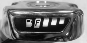
This kit fits '07-later XL models and replaces the front brake master cylinder cover on the right hand controls. It provides four levels of fuel from FULL to LOW, with the bars going dark. The lowest indicator will be lit near to the same time as would have occured on the Speedometer low-fuel indicator. When the sensor cannot detect a fuel level, the lowest indicator will begin to flash. Note that the Fuel Pump Icon will remain lit whenever power is on and is not part of the level indication. During the installation of the gauge, the Fuel Sender Resistor Assy is removed and the new gauge wiring is plugged into Connector 200B instead of the Resistor Assy.
This kit includes fuel gauge sensor 75093-09, which uses capacitive-sensing technology to detect the fuel level.
(Note that this part number has been superceded by sensor part number 61200040, which is also used in the 61200008A Sensor Kit. The reason for the change in P/N is rumored to be a required upgrade of the 75093-09 part due to a number of premature failures.)
For 2007 models (only) - If using either gauge kit with the stock speedometer, after the sensor is installed & the new gauge is connected, you must take the bike to the dealership to have the stock speedometer reprogrammed (using the DTII program to disable the low fuel light on the speedometer) so as not to interfere with the multi-level operation of the new Fuel Gauge Kit. The low-fuel light on the speedometer will stay on until the update is programmed at the dealtership.
If this kit is used with 2014-later models, wire kit 72673-11 is required.
(HD Install Instructions Are Here For Kits 75031-09 & 75338-09)
VSS - Modification for 1995-2003 12v Sensor
There have been a lot of issues and malfunctions of speedometers in these years. The below modification is intended to raise the voltage under load for the sensor as a possible fix for intermittent malfunctions. ( See this XLForum Thread which is related.)
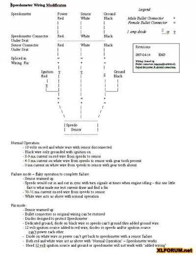 (CLICK on the image to see a larger version)
To see more information about the VSS signal GO HERE.
VSS/Speedometer Pulse Rate Converter
The Vehicle Speed Sensor produces a different number of pulses-per-mph between the 883 and 1200 models. The electronic speedometers on 1995-2003 model Sportsters were different between the 883 models and the 1200 models. Beginning in 2004, the VSS signal was sent to the ECM so that the ECM could be programmed to account for the differences between the models and send the right speed information to the speedometer.
Dakota Digital makes a product (SIM-1) to receive the pulses from the VSS and convert them to the appropriate pulse rate that is expected by the present speedometer. This conversion can help compensate for larger/smaller tires and different final drive ratios (changes in sprockets).
SIM-1 Product Description - Install Instructions
Apparently, S&S also had a conversion product (55-1007) that is no longer available.
XLForum Thread - Product Install
(As always, the links provided were functional at the time they were listed. Search the web for the product model if the links are inactive.)
Tachometers
See the Stock EVO section on Tachometers for additional information about using a dual-fire tach with a single-fire ignition.
http://sportsterpedia.com/doku.php/techtalk:evo:elec03#tachometers
Gauge Mods / Relocating
Headlight Eyebrow Mounted Gauges
The Zena Mod
This is a relatively easy mod to raise the height of your instruments (when using taller risers).
Otherwise, the gauges end up being too tall.
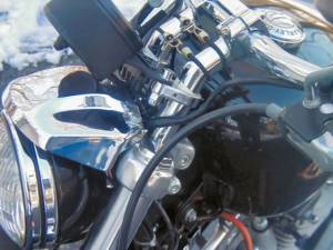
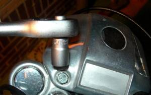
The gauges are removed from the handlebar mount and bolted to the headlight eyebrow using deep chrome sockets.
Cost is under #10. Done carefully, it looks like a factory install.
- Parts required:
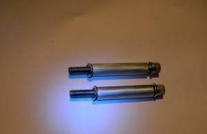
- (2) - chrome 8mm deep sockets (may be able to use other sizes)
- (4) - stainless steel washers
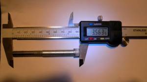
- (2) - 3” stainless steel allen bolts,
(same diameter as stock but longer to fit sockets accordingly. 3“ bolts used below).
- Note: This mod should work without a hitch on the 883 std and 1200R.
- In some instances, folks have reported that the spacing between the holes on the gauge mount
did not line up perfectly with the holes on the eyebrow. - Most were able to quickly remedy the problem with a dremel or other comparable tool.
- The mod will not work on stock 1200/883 Custom models without additional modification.
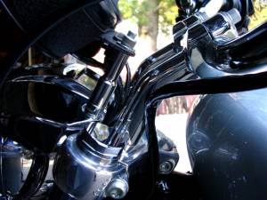 | 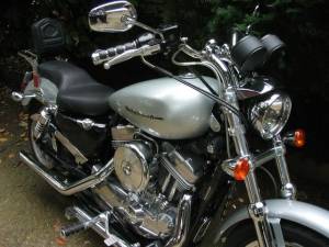 | 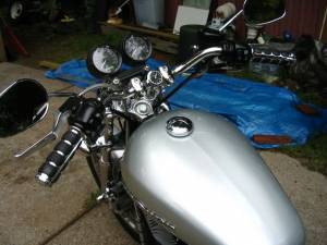 |
| Relocating gauges 6) | ||
Variation of the Zena Mod
| Before. 7) |
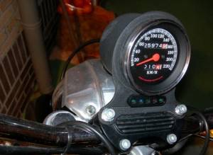 |
| After. 8) | ||
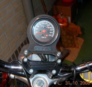 | 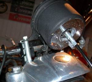 | 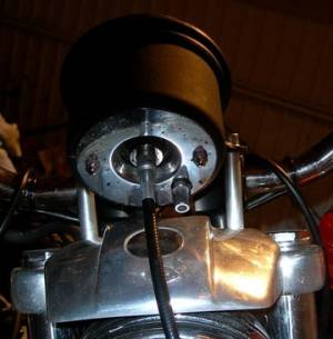 |
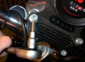
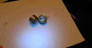
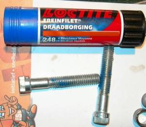
| Removed upper bar clamp bolts with a 1/4” Allen wrench. 9) | OEM Handlebar spacers (5736). 10) | Added blue Loctite to the handlebar bolts. 11) |
 |  |  |
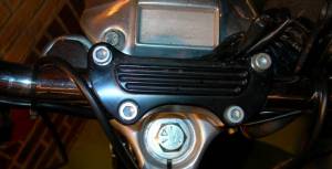
| Re-installed the bolts without speedo bracket. 12) | Removed the eyebrow bolts with a 1/2“ socket. 13) | Replaced the OEM bolts with 1/4”x3-1/2“ allen head cap bolts. 14) |
 |  |  |
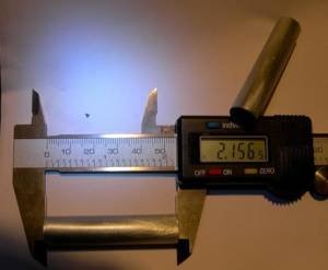
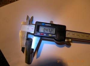
| 1/2” O.D.x1/4“ I.D. sleeves slid over the bolts with washers under the head. Sleeves go between the eyebrow and the gauge housing. 15) |
||
 |  |  |
Other Pics of this Mod
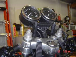
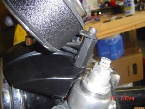
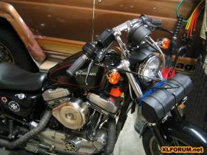
| Done on a 2001 1200S. 1/2”x1-3/4“ threaded rod couplers painted them black with 3-1/2” grade 8 bolts. 16) |
|
 |  |
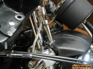
| Done on an 89 883. 17) | |
 |  |
Riser Mounted Gauges
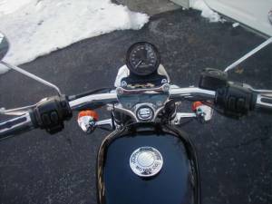
The ReddTigger Mod
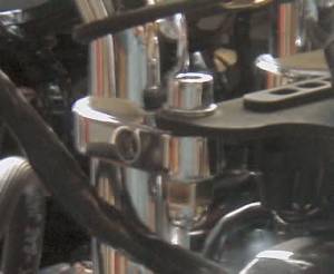
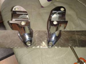
Speedo Mount for pullback risers.
The biggest frustration is the angle of the stock mount that's used to mount onto the original handlebar clamp.
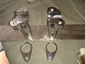
- Parts (total of about $20):
- 2 chrome socket head screws.
- 2 chrome acorn nuts.
- 2 chrome washers.
- 2 chrome cable clamps for 1“ (or whatever size your risers are).
- 2 small pieces of tubing.
- Place the tubing in the cable end of the clamp.
- Attach clamp to riser as shown below.
- Attach speedo using stock bracket (or any of your choice).
- Insert socket head screws w/ washers through stock bracket into hose in clamp.
- Secure with acorn nuts.
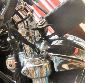
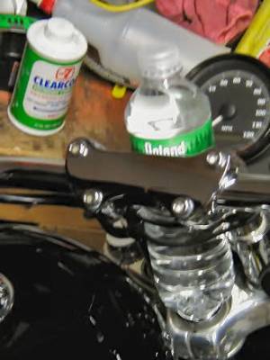
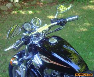
(the white stuff around the riser is some white electrical tape to prevent scratching) 18)
| A bungie cord across the bolts holds a water bottle in the middle 19) | |
 |  |
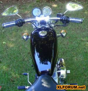
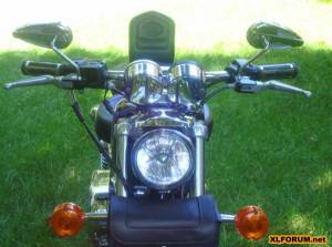
| Here's what it looks like with a tach added. 20) | ||
 |  |  |
Other Pics of the Mod
Handlebar Mounted Gauges
Adding Extra Instruments
Mounting extra gauges to the handlebars can provide monitoring for Head Temp, Oil Temp & Voltage.
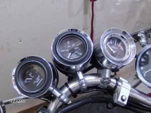 23)
23)
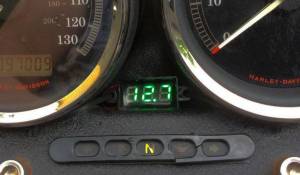
Adding a Voltage Meter
 24)
24)
Sportsterpaul of the XLForum wanted to monitor his battery voltage due to repeated charging issues. So he mounted a small digital meter between his Speedo and Tach so he could see his voltage while riding. As you can see on the Speedo (97,000 miles) he does plenty of riding.
These meters simply have a two wire connection (Positive & Ground) so you can tap into whatever voltage supply wiring is closely available to monitor the voltage on that circuit.
You should look to connect to the BLUE wire (Lights Circuit) or the ORANGE/White wire (Accessory Circuit - or ORANGE wire on older models) as the voltage supply.
From 2014-later (with the Body Control Module handling power distribution), you should look to connect your meter to the BLUE wire which is used for powering the front running lights. Remember, this power point is after running thru the BCM, so the voltage may not be exactly the same as at the main fuse. While the RED/Orange wire is from the Battery, you don't want to connect to it because that power remains live all the time (feeding the ECM/BCM/Etc.) and your meter would be running even with the Keyswitch turned to OFF.
Typical charging voltage (engine above 2000rpms) is 14 volts or more at the main fuse or circuit breaker.
