Table of Contents

REF: Service Procedures 9I
How to Blueprint Your Shifter
Article by Dr Dick 1)
I'll show you how to get great shifting and long trouble free operation from your 4 speed shifting system.
A factory XL 4 speed has one of the best operating shifting systems ever put on a motorcycle. Personally I think it is the best.
It doesn't need any improvement, though if your looking to get even better shifting integrity, read on.
There are common ailments that occur regarding shifters.
- Sheared pin on shift shaft (1973>).
- Broken ball stem on shift shaft (1972<).
- Shift shaft ball pops out of its nest in carrier.
- Top hats: broken, flatted, or brims getting distorted.
- Worn cam plate slots.
- Stuck pawls (1971<).
- Broken pawl axles welds (1972 & 1973).
- Broken centering springs.
- Cracked tower (1971<).
I'll address each item in addition to the blueprinting stuff.
This is the nomenclature I'll be using for each part.
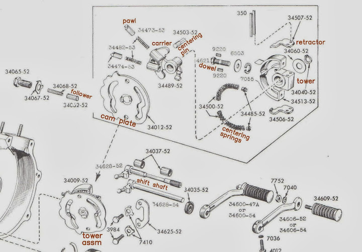 |
| Figure 1 |
The design change that happened in 1972.
 |
| Figure 2 |
 |
| Figure 3 |
The entire shifter mechanism does one thing, slides one gear axially along the mainshaft or countershaft.
These gears have a specific amount of sliding movement that the cam plate provides.
When at the extreme ends of sliding travel, the dogs on the gears engage and your bike is “in GEAR”.
When slid to the center of travel, you're in neutral. No dogs engaged at this position.
When “in GEAR” the engagement dogs hold themselves engaged. Your shift mechanism does not hold your bike “in GEAR”.
The logic we will follow begins at the gear sliding along the main or counter shafts and ends at your toe.
So the 1st parts we are going to look at are the forks because they slide the gears along the shafts.
Shift Forks
Shift Fork History
The infamous shift forks.
I can't tell you how many times I've heard “my shift forks are bent. I need you install some good ones that won't bend inside a month”.
When I hear that I'm sure I'm dealing with a barstool bench racer.
Why? Because it's exactly the same as this:
“I need my car wrench to install some new front tires on my cage that wont wear bald on the inner side of the tread within a month”.
As if it's a tire problem. We know better. It's an alignment issue that's causing the problem. The tires are collateral damage.
Just like your cage tires- WORN/BENT SHIFT FORKS ARE COLLATERAL DAMAGE OF OTHER PROBLEMS.
95% of the time, it's worn dogs. 5%, it's dragging clutches if it's the 1-2 fork showing wear.
I'll come back to wear.
There are 4 OEM shift fork configurations. My criteria regarding forks, what do I use?
The L1970> OEM alum bronze are my favorite but the e1969< OEM are good too.
Question:
- brucstoudt: I realize you have your personal preference for the bronze aluminum alloy forks, but from a strictly wear resistant point, wouldn't the steel forks be more wear resistant than the non-ferrous forks?
- Dr Dick: I don't think so. In a correctly working transmission, there is very little fork wear. It took over 20 very high mileage years for me to wear a fork to what I considered wiped out. I've only seen the kind of mileage it took on one bike in my life.
The wear was at point C (pic above). If your preference is for steel, that's Ok. They work good. Either material will last for the lifetime of your bike if transmission is set up correctly and the clutch is dry. I know for fact on wet bikes the bronze wears slower at A. Seems they handle lower oil viscosity better. Low oil viscosity seems to accelerates wear at far side A on the 3-4 fork. Or maybe it's the reduced contact area on the OEM steel forks at A.
The hat pin seems to be more wear resistant when its steel. Either way, on any bike, you're talking lots of years/miles before any fork will need replacement. I honestly think it's a non issue.
I'd go with what your guts say on the material.
On a side note about OEM forks - bronze ones flex less due to the added gusset that the 3 pc units lack. Does that rigidity help anything? I never noticed any difference on a street ride.
- The 1952 style, I believe these were used 1952 & 1953 but I'm not sure. I don't have an example to post.
They look like the the next pic but not as beefy (if you know about these your a real K nut). - This is the second style used 1954?-E1969. 3 pc welded steel, carburized, heat treated, and tempered back to around 40rc. This is the venerable HD 'steel fork'.

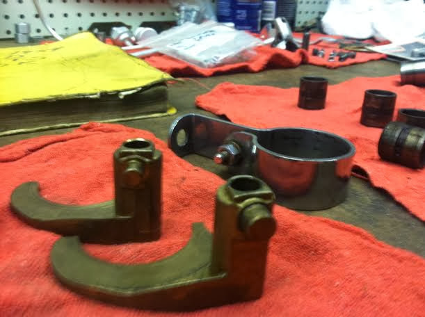
- L1969 and early 1970. The 1st aluminum bronze forks (if you know about these forks you should be writing this thread) VERY RARE. It's the NOS one in the foreground. The rear one is the L1970>. Can you tell what's different? The “pin” on the end is bigger on the one in the foreground for the tophat,finger roller. But the part's book only show's one p/n. The L69 fork didn't use any tophat. The fork pin rode directly on the cam plate. That was a dismal failure. The old top hat returned very quickly.

- L1970>, one pc aluminum bronze.

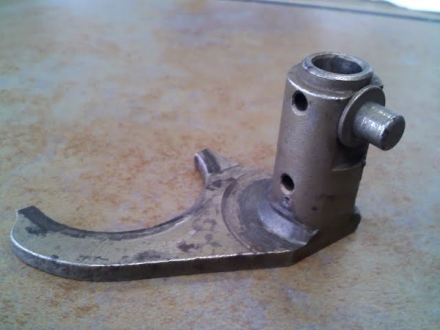

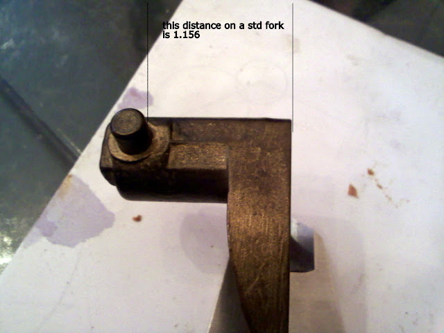
Starting in 1972, these forks were supplied in plus or minus .020“ lengths from the parts dept. (all factory bikes came with standard length forks).
Shift Fork Geometry
A little food for thought about the blueprinting mindset:
I often hear that blueprinting is getting all components in the “as designed” positions.
And that's a great starting point.
In real world use, blueprinting is more about bringing parts into an attitude where they interact best with their mates so the system works best as a whole. In this case we want our toe to slide a gear into engagement. This thread is about just that, connecting your toe to your gears.
In that line of thinking, we really can't look at a single part as a single part. It's connected in a sort of mechanical chain of many links. So each link needs to “act right” where it meets the next (or previous) link in the chain. That's your mind set and your goal.
As we dissect each part we gotta look at it's next door neighbors simultaneously.
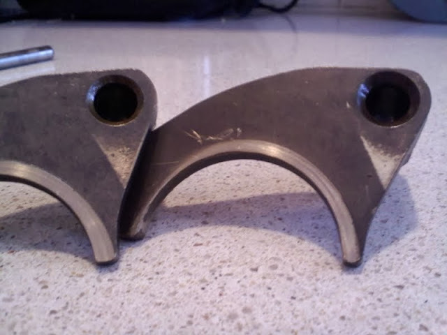
Here's a fork with 3 wear areas shown below. Its “A” that most people are concerned with. But it's irrelevant for this thread. Except to say excessive wear at A requires replacement and repair of the generating cause.
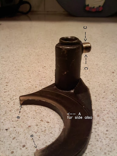
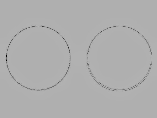
Let's focus on B, the wear on the inside of the fork crescent. See the little triangle? It will be on the opposite side also (the 2nd B).
That comes from “fork rotation”. The large full circle is the groove minor dia in the sliding gears.
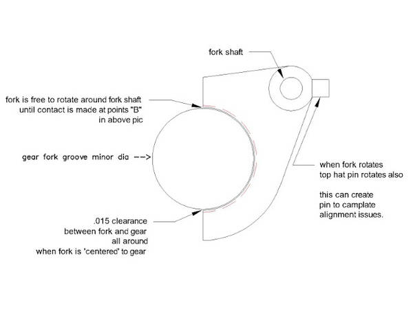
If wear at B gets too great, the fork is allowed to rotate more = more top hat to plate misalignment.
What if:
a) Your no name a/m fork is made like the red dashed line? Way more fork rotation that's what.
b) Hat pin is not in correct position in regards to the rest of fork? Now top hat isn't positioned in cam plate correctly.
Fork rotation is bad, as is incorrect hat pin location. Both need to be minimized.
How does the wear at B occur? When you shift, you rotate the cam plate.
The hat ramps in the plate force on the tophats. Tophats push on the fork pin.
But the action between the ramps and the hats wants to create fork rotation.
So the forks do rotate around the fork shaft on each shift. It's points B that limits the rotation.
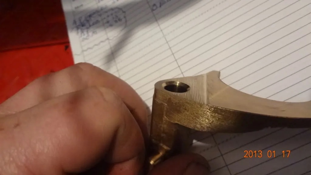
The wear at C. Given enuff time, the pins will wear from tophat rubbing at points C.
Good finish on pins and inside hat bore will minimize that.
(L) See the shiny triangles just below the fork shaft hole. (R) That's from this.
This can happen in 2nd or 3rd gear. I relieve both forks just enuff to get some clearance.
DirtyCory relieved his about .020” off each one.
 2)
2)
Question:
- mct496: Just checked my forks. No signs of wear at “B” but the one has @ .125“ of movement! ! A/M.JUNK!!
Are there any good a/m out there or do I need to start looking for OEM? - Dr Dick: Yes a/m junk. And I finally get to illustrate why the 'no name' a/m stuff is junk. mct has got a fork that has too much rotation. It's because the cresent isn't in the right place or isn't the right size or both. It costs just as much to make that fork with the wrong dimensions as it would have to make it with the correct ones. Any supplier knows that parts that fit and work correct are better for his business in the long run. That begs the question “why not make it correct from the get go”? Because they can't. That's why.
Here's why: Rude Rudy, owner of ameraisan mc parts co., calls the rep from the peoples republic of cheap products ltd. He wants to get forks made. Rudy hands a fork to the rep and says “copy this and send me 500 pcs. How much and how long? Off goes the rep. Somewhere in prcp ltd a manufacturing engineerer makes a virtual artifact of the sample - either a 3d model or a set of “blueprints”. He has reverse engineered the fork.
The prints go off to production where the dept head needs feature tolerances to work within. The tighter the tolerances, the longer it takes to make 500 pcs. prcp ltd. needs to keep production time short for it's bottom line.
Production meets with engineering to discuss the tolerance dilemma. Engineering doesn't know what the part fits. To them, it's just another widget they are copying.
Engineering calls the rep who in turn calls Rudy to get the required info. Rudy also doesn't know any of the below dims either.

But he does know if he makes the fork “sloppy”, it will assm to bike. If he makes it too “tight”, they wont fit. Too tight is a disaster for Rudy. He just paid for 500 parts that can't be used. Every one he sells will be returned for refund. Rudy is out big bucks.
Rudy explains this to rep. Rep says he understands and asks Rudy the $64,000 question- “what do you want us to do?”
Rudy replies the only way he can “make them good and sloppy so they will definitely assemble” and hangs up. Under his breath Rudy mumbles to himself “these Harley guys who are gonna buy them wont know the difference.”
Turns out Rudy is right - most guys don't know. But the guys who read this thread will.
I won't be replying to any posts regarding the politics of the aftermarket in this thread. This thread is for the end user of the parts we are dealing with. He needs practical info he can use on his workbench.
The info I laid out on the forks should give you guys a mental yardstick in determining how well the forks you posses are going to operate. Remember: even bikes chock full of a/m junk still shift pretty damned good (that's testament to the design of the whole system). Getting some nicely made forks is the best a home builder can do. I'd suggest you go OEM on this.
Top hats
Side note from DirtyCory: 3)
This was a good idea that DR DICK clued me in on when I was rebuilding my 78. Using big twin top hat rollers instead of the sportster ones. At the end of the sportster roller there is a chamfer that don't make contact with the grooves in the shifter cam. The big twin is exactly the same except for longer. So grind the big twin to length and utilize the complete surface area of the shifter cam.
The part# for the big twin top hat is 34168-39 4).
Top Hats 1
The tophat. It's an important component often overlooked or considered a nickel/dime part.
Big mistake. Because it's the tophat that controls the fork.
I believe tophats are very important to long service intervals. Crappy hats just don't last. And the factory ones, while good, did have some quality issues, mainly with surface finishes. Rough surfaces wear quicker. It seemed HD made them as nickel/dime parts. So there were nice ones and crappy ones in any HD bag of 10pcs. In the chain of parts I referred to earlier, the hats are the weakest link. When hats fail, your trans goes down.
In a correctly working trans, the loads a hat sees isn't extreme in a wide view but they a small parts with small bearing surfs and very thin sections. So in their little word small loads seem big and small increases in loads are big to them. What you wanna do is anything you can to make their life more bearable. When you succeed they will do the same for your life. This paragraph is key to blueprinting these parts. You might wanna re-read it.
To explain what you need to know, let's look at what happened to sportster Sal.
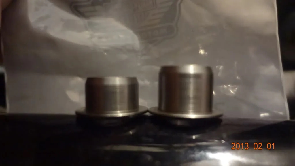
Sal put some new soft a/m hats in his bike. Rode it for a season, then pulled the trans. His new hats look terrible. They have flat spots on the OD. The entire hat had grown in size to where it started to hang up in the camplate. The growth also made the ID fit-to-fork pin greater and the brim was all worn.
What happened?
Material Background:
To explain that, we need to understand what used to be called “machinery steel” (I'm gonna keep this short with just enuff condensed info for you to grasp what's going on with tophats). This machinery steel is what your going to encounter a lot throughout the shifter (really through out your whole bike). Machinery steel now classified as either carbon steel or alloy steel. They are very different yet very similar at the same time.
These steels are really modified iron, as they all contain 96% or more elemental iron. Elemental iron isn't the cast iron your familiar with. It's a very soft, very malleable metal with low strength. It reminds me of lead but a tad stronger and lighter. It's so soft it's useless for mechanical loads. Alas this whole planet is made from it.
Recipe: 100lbs of elemental iron and heat it untill liquid, stir in 1/4 lb of carbon and 1 lb of manganese. Let it cool.
What you got now is an alloy of iron. It's 3X as strong as the iron you started with. Pretty damned good for a pound and a quarter of spices. What's it called? Mild or Low carbon steel. You can make your mild steel a bit stronger yet by hammering it, or squeezing it some other way, like between rollers. Ever hear the term 'cold rolled steel'? Though it only gets a little stronger and that strength is erased by heating it. This stuff will be great for gas and oil tanks, fenders, wheel rims, even frame tubes. You can get the stuff red hot and plunge it into 29 degree sea water and nothing happens to it. (too bad there's no application for that) but it needs to be stronger for use inside your bike.
So, re-melt your mild steel and toss in another quarter pound of carbon. Let cool. Your steel seems to be just like before though it get a bit harder yet when hammered. You still loose the hardness when heated allow it to cool in still air. So you try the heat and water quench - sumbitch it gets hard and stronger. ye-ha. You make a drill bit from it and drill holes in your low carbon with it (until the tip of your drill gets hot then its all over). Got sumtin going now. It's called medium carbon steel.
Round 3 (high carbons).
If 1/2 lb total of carbon is good, what about 3/4 lb total? Re-melt. In goes another 1/4 lb. and cool. It's stronger. ye-ha again. You try the heat and water quench - it gets harder yet. Drill bit made from this will drill your first two steels but is prone to breaking if you're not careful.
Round 4
Re-melt. In goes another 1/4 lb. - 1lb total, and cool. It's real strong. ye-ha again (or so you think). But your steel now begins to crack when hammered. And you cant weld it. You try the heat and water quench - its gets REALLY hard. Every drill bit breaks immediately. It's like glass. So you make a straight razor from it. Lasts so long you pass it down to your son. But it won't tolerate any flex (read as deformation). It snaps in half at low loads. Loads so low it's useless for most mechanical uses. Sumbitch, ain't that where we were with the elemental iron - useless for loads?
What did you learn from all this? That steel can be made harder by changing the recipe and heat treating it. That would be very useful education if you could tame the increasing brittleness goes hand in hand with the hardness/strength increase. And you can. You go back to your two 1st steels - the low and the medium carbons. Re-melt. Add 1/4 lb molybdenum and 1/4lb of chromium. You got your chrome-moly alloy of steel. Melt this down add in two lbs of nickel and you got one of the strongest steels known to man 'ni-chrome-moly'. In heat treated form, it can exceed 10X the strength of elemental iron and it's still 96% elemental iron.
Steel really is some amazing stuff.
Ok, what happened to Sal? His hats weren't hard enuff. What does that term “hard” really mean? Hardness is “resistance to penetration” (try to stay focused on your bike will ya). How can you penetrate steel? You deform it. A center punch mark is deformed and penetrated steel. Try to center punch a ball bearing. Can't do it. Not easily any how. Got that?
Sal's hats were too soft and they got 'cold rolled' by the camplate when they had to carry loads created by having to force ever so slightly worn dogs into engagement. The small rounded edges of used dogs (male and female) tend to contact each other during the beginning of engagement movement. These worn areas want to ramp apart and send large forces back to the hats. The hats need to be hard enuff to resist deformation, but not so hard they they are brittle, because then they would break.
If you had hard hats with thicker sections, they would be much less inclined to break. That's the material background.
Hat Geometry:
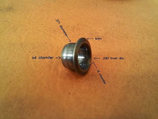
We know it will have to carry loads concentrated on very small areas. I strive to increase those areas. Let's talk about how the hat fits to the fork. Here are 2 top hats slid over two fork pins. The one on left has .002” running clearance,
right has .006”. You can see that the “arc of contact” is going to be larger on the left one. This will spread load over larger area = less per unit of area loading = less wear. It also holds fork snug so there isn't as much room for the fork “swing its hammer”. The size of the load bearing area is also influenced by surface finishes of both parts - the hat bore and the fork pin. Ruff finishes = highspots = less surf area actually carrying the loads. A good tight fit of .001/.002“ helps tremendously.
Look at the pic. See that giant ID chamfer? That's lost surf area. I don't like that. There needs to be some kind of chamfer to clear fillet at pin base. Small as possible is best.
Top Hats 2
In the last post I talked about how the hats were made and how they fit to forks. This post is about how they fit to camplate.
The camplate has grooves that the hats ride in. If you look at the active top hat position when in 2nd or 3rd gear you will see that any disengaging forces (generated by worn dogs) force the hat onto a pointed area of the plate ramp. The sharp point on the plate greatly reduces the contact area on hat outer diameter. Very high “per unit size” force is generated at this interface. This is where hats get their beating.
- If hats are soft, they get deformed.
- If hard, they can take the load.
- If too hard, they can shatter.
In the case of the soft hats, the material just cant take it. In the latter two failure DOESN'T come from degree of hat hardness. Failure in these cases stem from overly worn dogs backloading the hats to an unsafe level. That means if your breaking hats, your dogs are overloading them. It also means the backloading is wreaking havoc on the rest of the system too. None of this is good AND NONE IS THE FAULT OF THE SHIFTER SYSTEM. Fix your dogs. It should be apparent that short lived or beat up shifter components most often come from worn gears.
Let's say your gears aren't wearing at any appreciable rate. This is the case in bikes with dead dry clutches. In these bikes, the shifter parts lasts super long. All the wear comes from high mileage. Never the less, increasing contact area between hat and plate helps every bike regardless of gear wear.
The plate is .220” wide. The .371“ hat OD length is also .220” long.
But that big OD chamfer reduces the contact area to sumtin quite a bit less than .220“. That's where using shortened big twin hats gets you better life - no more OD chamfer. Although the BT hats still have a large ID chamfer. For a home builder, the BT hat deal is a no-brainer. Grind hat length so they span the plate width. \\But that big OD chamfer reduces the contact area to sumtin quite a bit less than .220”. That's where using shortened big twin hats gets you better life - no more OD chamfer. Although the BT hats still have a large ID chamfer. For a home builder, the BT hat deal is a no-brainer. Grind hat length so they span the plate width.
For the guy with a lathe - make your own hats. It's well worth the time. This way you can achieve very precise fits and finishes. That means very high load handling and very long life. This also means you can make brim thickness to suit your situation as well as eliminating both the overly large factory chamfers. Use o-1 oil hardening tool steel. Make sure you provide a small radius fillet at intersection of brim and diameter that fits into plate grooves. Polish all sharp edges from hats prior to heat treating. You make your diameters and lengths to fit your mating components. Forget the factory numbers in the above pic. After you make and fit hats as above - hang one on a pc of non magnetic stainless steel welding wire. Heat hat with propane torch til it starts to turn red. As you continue to heat it, check it with a magnet. When it becomes non magnetic, quickly quench it by submerging and swishing it around in an oil bath. A half full soda can of motor oil is plenty. Repeat with other hat. When you lay a file on these you wont be able to cut into them if you did everything correct. Now heat your oven to 400 degrees. Hang hats in there on wire for 90-120 mins. This tempers the hats (draws back the hardness a little).
Done. You can get o-1 steel from your local industrial supply house.
This hardening procedure probably won't work for, say, J&P hats. And if by some freak chance the steel they use does contain enuff carbon to get hard, will it get brittle too? That's a very big question. Your bike is too precious to use as a guinea pig to find out. For steel to be hard and tuff at the same time requires a steel formulated for that.
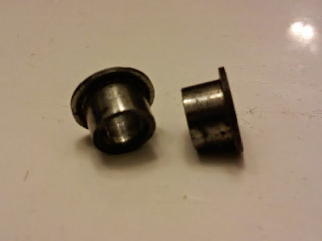
Making your own top hats is not obsessive compulsive. In the pic below, forgive the rust.
These used home-mades have been in the top drawer of my tool box for at least 30 yrs.
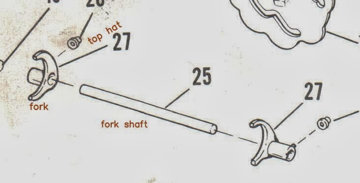
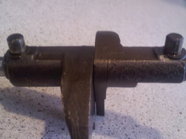
Fork Shaft
We have talked a bit about forks and hats. When the forks and hats assm to bike, they register on the fork shaft.
So it's the shaft that sets position. The shaft must be straight.
One end of the shaft fits into a hole on the door. The other end into a hole on the case.
In the fsm it says not to remove the shaft from its press fit in door.
Why? Because they don't want your shaft to get loose in it's bore. The shaft position is one of the things that sets gear spacing by setting the relationships between the top hats and the grooves in the camplate.
If your shaft is loose in door bore, the far end of shaft isn't held in a solid position. This shaft weave can effect the 1-2 neutral position when setting gear spacing on the bench. Compounding this is the fact that the 1-2 groove in camplate has two neutral position that may or may not give the same sliding gear position along the countershaft. I'll get deeper into this as thread progresses.
A tight shaft gives (in theory) the same shaft position on bench as in bike. If your shaft is loose in door to the point it wiggles around do this - apply loctite to door bore and door end of shaft. Assm door/shaft into case and tighten door bolts. NO FORKS. This holds shaft in position till loctite kicks. Having a tight shaft should make life on the bench easier.
Cam Plate
Cam Plate 1
Earlier, I put forth the proposition to think of your shift assm as a chain of many links. Well now we are at a point where links dont have to interact just with thier nextdoor neighbors. No more vis a vis, links farther from the camplate will effect the camplate.
Some geometry:
Notches:
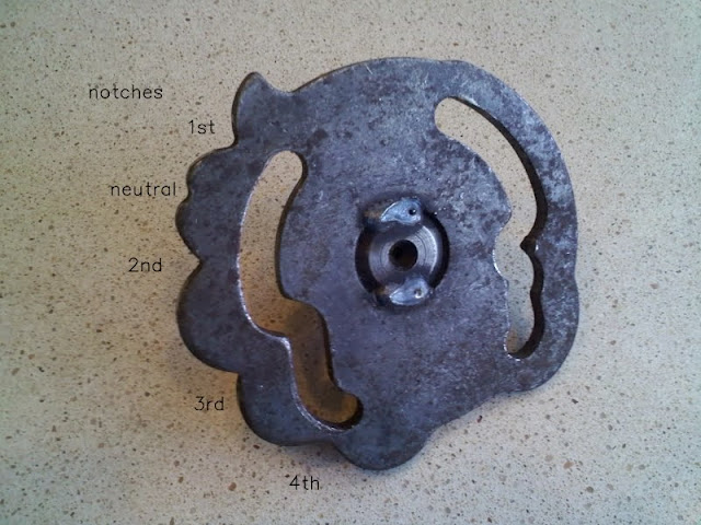
Slots / Grooves:
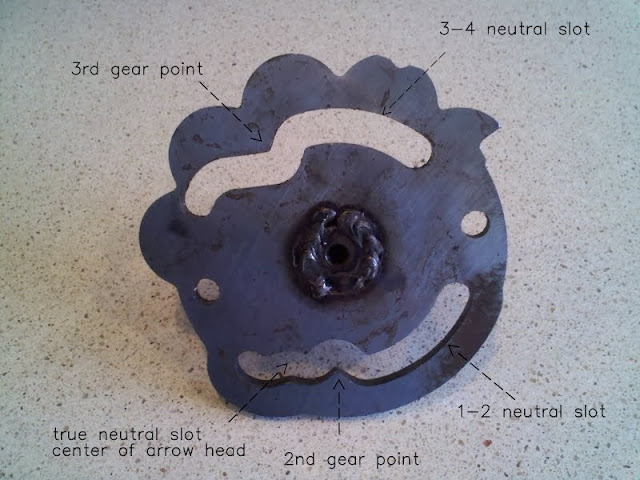
Relationships:
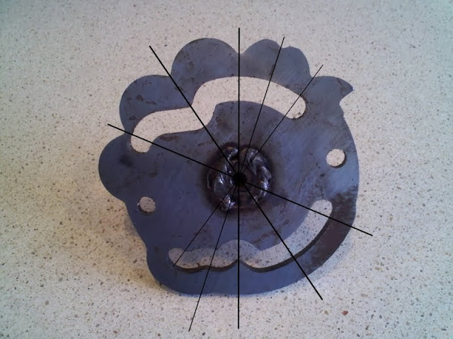
This is an important picture. Study it.
- Note that the slots and the notches have a definite relationship.
- Note that the 1-2 and the 3-4 neutral slots are concentric to the center of plate rotation and the true neutral is not.
- These relationships are mirror image on XLCR. The cam plate is flipped over when welded to the axle so the shift pattern remains 1 down 3 up with the flipped shift lever.
Let's take a look at camplates used thru the years.
The differences in the 1970 to 1971 change is subtle. The 1971-1972 change is pretty obvious. Can you spot the changes?
1952-1970:
I have purposely rotated the plate to position unobtainable in normal operation to show it's features better.
1971:
(disregard all else but the cam plate as this pic was from a members bike that has many year parts intermingled).
Some guys prize this plate for it's soft yet positive full throttle 1-2 shifts.
(remember fictitious sportster sal and his soft top hat from the earlier post? see that top hat?).
1972-1974?: (I think is was 1974. My memory is slipping.)
1975:
Cam Plate 2
Alignment of ratchet teeth (on hub) to follower notches.
Thing to know here is that plate and hub is two pcs welded together. This means there is an alignment that needs to be maintained. See how the teeth are to be centered to the notches. This alignment has been accomplished thru various means at the factory. What's important to us is “are the teeth aligned”, not how they were done.
Some plates will have slight misalignments. Depending on other alignments (that we haven't gotten to yet) this can show as a “pawling bias”. Pawling bias allows a more positive shifting action in one direction (up or down shifting) by stealing from the other. You want even bias. Even bias gives you positive shifting in both directions.
Cam Plate 3
- doodah man: 1952-1970 has a more “pronounced” neutral detent for the cam follower, since that's all that holds it in neutral. A touch higher on the 2nd gear side of N. Both sides of the neutral detent are flattened on the 1971.
Dr Dick: Exactly. But why? Could the 1971 change have to do with the new wet clutch? The wet can be problematic in finding neutral. If this was driving the change it sure looks like the 1970< plate would be better, don't it? I gotta think this isn't the reason. - gpsjr10: The welding to the shaft is different unless someone added weld to the first one.
- doodah man: Change from 1971-1972 up adds an isolated -N- spot to the slot in the cam to help keep the shifter in neutral.
Dr Dick: Yes, the groove between 1 and 2 is different. You would think it has to do with neutral. But I have come to the conclusion it's got nuttin to do with that.
For 19 yrs, the same plate was used. That's a long time. After 19 yrs, there is a neutral issue? Not likely.
After I learned how to keep 1970< clutch truly dry I noticed sumtin. A well used totally dry OEM clutch wont have any drag. Zero. So when you pull lever to go for 1st, the gears can be stopped in a place where the dogs aren't aligned, like shifting a non running stationary bike. No engagement. Shifter just stops half way. Let the clutch out a little and gears spin - click - got 1st now. This same thing can happen on the 1-2 shift at low rpm gear change.
If it wasn't because your clutch is working so good that this problem develops - it would be pretty aggravating. Polishing dog/gear faces so they slide easier across each other helps. Thing is that switching to a 1972-1974 plate nearly eliminates this problem. Why?
Because the new “longer” neutral slot delays engagement movement until plate has rotated more. That forces the gear movement to happen quickly near the end of plate rotation.
What if your draggy wet clutch and slightly worn dogs have slow engagement? They bounce off each other and your gears grind. This does happen on 1971's and 1970< with draggy clutches. You see those guys really stab at the shifter in order to create that missing engage speed. While dry guys just snick into gear.
If you use a 1970< plate in a wet bike you will find neutral much easier. But you gotta be deliberate goin into 1st.
Cam Plate 4
Everyone likes a bike that “shifts like butter”. For this to happen you need:
- All the previous posts heeded.
- A clutch without excessive drag. Some drag wont effect shifting, but too much will.
- Actual gear engagement points that sync to plate position correctly.
#1 should be obvious. So should #2. Let's look at #3.
This is the follower. It slides in a screw-in housing. It must slide freely. Remove it's spring and check for free. If it binds, that must be dealt with. Often over torqueing housing will distort housing (go back to the top of page if you need to refresh all the part names).
This is a 1970< plate in the 1st gear position.
There is definite evidence of some kind of tower issue here.
See the deformation of a hardened 3rd gear tit and the phantom wear marks surrounding the 3rd gear area of hat groves? We will get to this later.
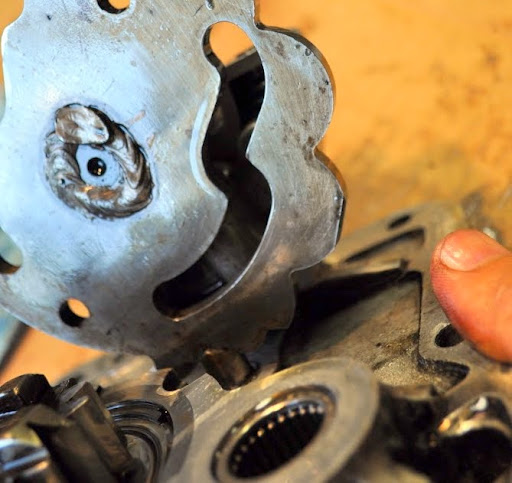
See how the plunger is extended (by its spring) and is holding the plate from freely rotating. When you shift, your toe rotates the camplate. To do this, the plunger (the follower) must be pushed into it's housing, compressing it's spring. You supply the power for this by moving the shift lever.
Once you have rotated the plate to the point of maximum follower compression, the follower “goes over center” of the cam plate notch hump. At this point, the follower “snaps” the camplate into the next gear by the spring forcing the follower to extend. So, your toe supplies the 1st half of gear change camplate rotation and the follower provides the 2nd half. Basically, you disengage the current gear and the follower engages the next gear. Got that? It's important.
When the dogs contact each other during the “rider controlled” portion of plate rotation, you will feel this contact in your toe. It's the classic “notchy shifting trans”. Conversely, when the dogs contact each other during the “follower controlled” portion of plate rotation, you feel nothing. Butter. If you think about this gear spacing has something to do with smooth shifting.
Any one familiar with these transmissions know they can get some very deep dog engagements by some workbench trickery.
Deep engagements (if dog face angles are congruent) can safely pass lots of power over long time intervals. As a side effect, the shifting gets “notchier”. Once HP climbs to 75, dog integrity become very important. At 100+hp, it becomes paramount.
So a “nice buttery” trans may be an iffy proposition for bike making big numbers. But, for the vast majority (read as stock displacement) this heavy duty trans gives no reliability increase. If this is your case leave the notchiness and opt for the butter. It's a joy that big HP guys often forgo in order to keep their gears off the pavement.
Shifter Pawls
The pawls. What they do is act as a ratchet.
From an on-line dictionary: A ratchet is a device consisting of a bar or wheel with a set of angled teeth in which a pawl, cog, or tooth engages, allowing motion in one direction only.
In our case, one direction is upshift rotation of camplate, the other is downshift.
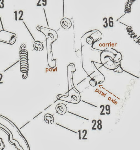
Pawls came in two designs: \
- Plunger 1971<. #30 & 31 (the illustration below shows these pawls in a incorrect order of assembly)
- Claw 1972>. #29 in the illustration.
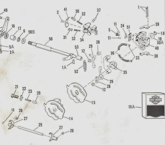
The claws are unidirectional, while there is dedicated upshift and downshift plungers.
Plunger pawls can bind in the carrier bores (wee will address this in the carrier posts), the claws are immune to this operational defect.
When your shifter is at rest, both pawls are engaged to the ratchet teeth on the camplate. So either up or down shift can be initiated. As you move the shifter with your toe, the one of the pawls grabs a ratchet tooth and rotates the camplate. Let's call this the active pawl. The other is the passive one.
When the follower goes over center (see cam plate 4 post for this) the passive pawl needs to be taken out of contact with camplate. One of the retractors (#38 or 39 in the illustration) does this.
Disengaging the passive pawl allows the follower to accelerate the camplate rotation faster than your moving the shift peg. This is your buttery shift in action.
When you release the peg the pawls rotate back to the “at rest” position. Some time during this return motion, the active pawl needs to ratchet to the adjoining tooth on the camplate. If this happens too close to the at rest position of shifter, you may not actually get this ratcheting every time. This will lead to a phantom (missed) shifts on next sequential shift. A stuck pawl will also do the same.
Getting the ratcheting to happen with precision timing is the result of many mechanical interactions. To address this situation, you need more info than what has been covered so far. At or near the end of this thread we will come back to this important performance point.
The pawls are loaded against the camplate by springs. #32 or #52. Rarely the #32 spring will break. Inspect these. Don't stretch them or use one that have been stretched. I've never seen a #52 spring failure.
For guys with 1952-1976 bikes, either style pawls may be fitted providing you also install the matching carrier (#34 or #35) and springs. This is gonna bring up the inevitable “which one are better” question. Actually this doesn't apply to just 1976<. By shortening the hub on the carrier, any 1976< carrier can be used in the 1977> tower.
It's a buck dancers choice:
The claws are idiot proof - they always seem to work for street use.
The plungers are beefier but they require some craft to work flawlessly. (wait for carrier posts).
I've seen some claw type carriers bend and break pawl pins loose on air shifted dragsters.
Plungers by design need to ride in bores or guides. If you look at the at rest position of carrier you see this:
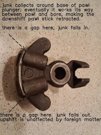
The major polluter of trans oil is wet clutches. The 2nd biggest problem is errant nylon from primary chain skid shoes.
Recommendations to preclude stuck pawls on 71<:
1a) Run the 72> claws instead of the plungers. These never stick. See carrier post for the correct vintage to fit.
If you decide that you'd rather have the super duty shifting provided by the plungers, other things need to be done: \
1b) Every one should be running flat sided primary chains - they don't tear up skid shoes.
2b) Use a dry clutch. If that's not gonna work for you see 1a.
3b) Recreate the 1952-1957 hardened skid shoe.
Carriers
Carrier 1
There are 4 different versions of OEM “pawl carriers” and 5 OEM versions of the “pawl carrier support” (I call this part “shift tower”). 5)
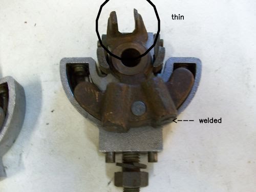
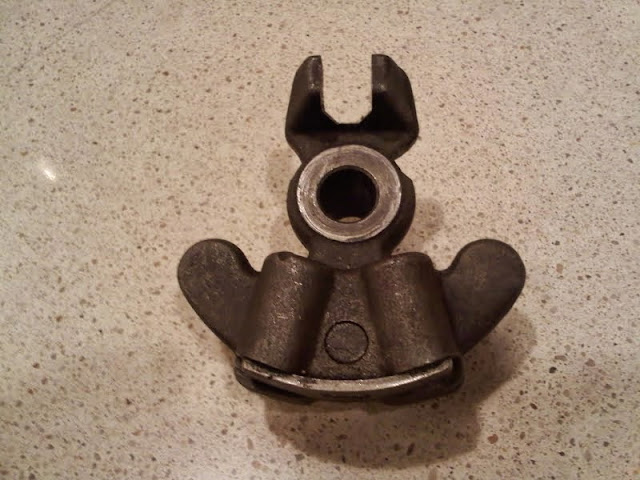
This is the 1952-1953 carrier.
The thin area renders these unsuitable for 54> cases. The 1952-1953 cases used a bolt in stop (34625-52 in 1st post) that limited shifter shaft rotation. In 1954, that part was dropped and carrier rotation stop was moved to contact between carrier and retractors. In 1966, this was beefed up. More on that to come.
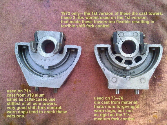
1954-1971 carrier.
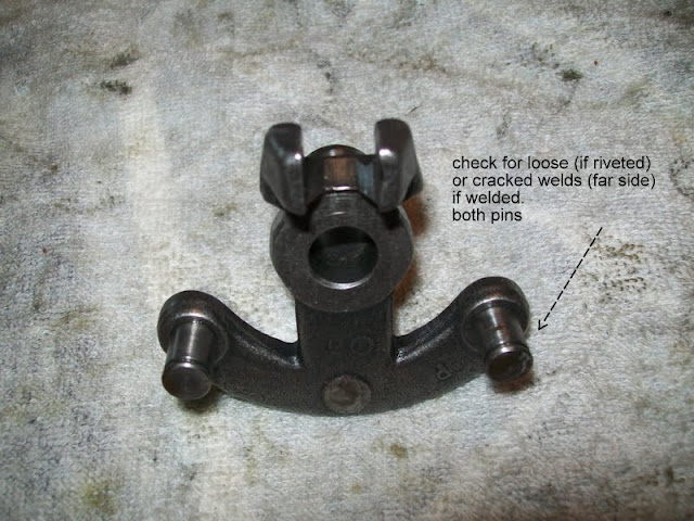
1972-up carrier.
Areas of interest.
- The thru bore for camplate axle.
- The journal surrounding the thru bore that fits into the tower.
- The stop area.
- Pawl bores (71<) or pins (72>).
- Location of centering pin.
Symmetry. When assmed operational symmetry between these parts become important between;
Pawls
Retractors
Camplate teeth
Due to manufacturing tolerance, stacking operational symmetry can be compromised.
After explaining how the symmetry can be screwed up, we will talk about repairing it.
I'll take a bunch of pics to illustrate all the relationships.
To do that, I'll need to jump ahead to the tower geometry then come back to the carriers.
Carrier 2
When building a bike that's gotta deal with the real life of a hardened biker ruggedness becomes important.
No one I know wants their bike to give out before they do.
When beaten by miles and smiles you want your bike still working to drag your sunburned ass back to the couch.
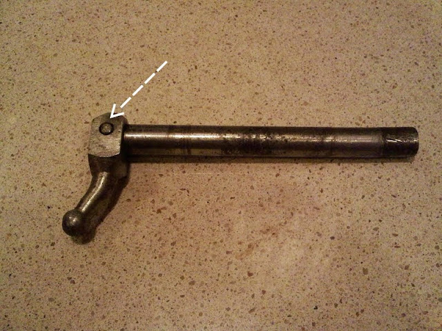
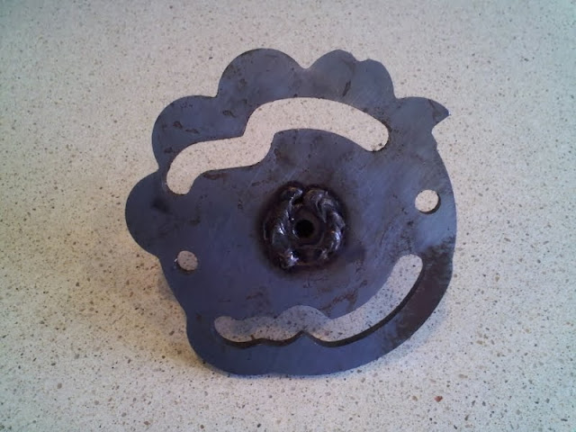
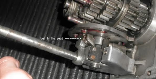
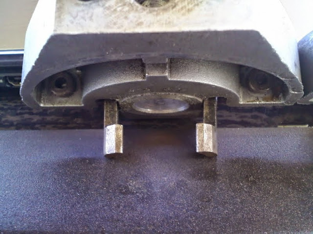
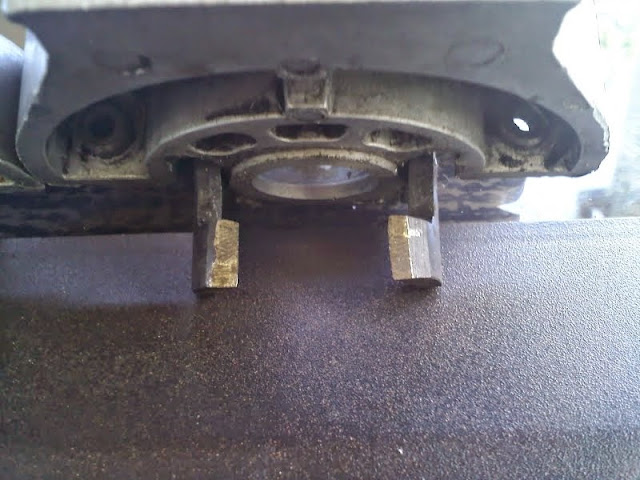
Fact - bikes get dropped. If your shift peg down and the peg catches you can:
(A) Pop shift shaft ball out of carrier seat.
(B) Break ball clean off.
Either of these will end your fun. Let's deal with 'A' 1st.
If you own a 1952-1953 equipped with OEM stuff, this isn't a problem as the bolt in stop wont allow the ball to force it's way out of the carrier seat. But you have other problems. The shifter lever is splined to the shift shaft - limits adjustability of peg position and production variances between position of stop to position of seat may limit shift shaft rotation. So that full carrier rotation is no longer assured = missed shifts.
The factory got away from that scene on production bikes by dumping the case stop and allowing the carrier rotation to be the limiter. Now the carrier can always rotate it maximum. Dropping the splines got rid of the position adjustability issue and added a slip joint between lever and shaft providing you didn't torque the shift pinch bolt as if it's a crankpin nut. This slip joint saved your weekend (the racers continued to use the splined shifters).
Alas, HD guys aren't the most finesse-full. So the pinch bolt got creamed solid and balls popping from seats resulted. Look at how thin the seat is in the pic at top of this post. This thin section flexes and popped out ball is the result when used with no case stop.
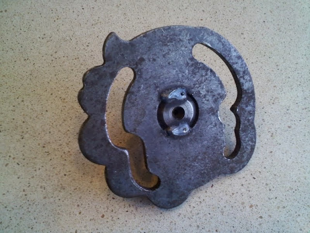
How? \
Look at these pics. They show the carrier at it's limit.
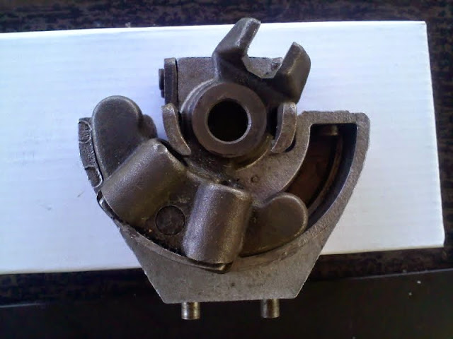
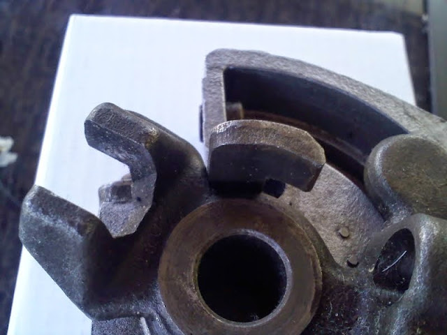
See this? It's the carrier at it's stop. Read that as:
This is what stops your shift peg travel, both upshift and downshift.
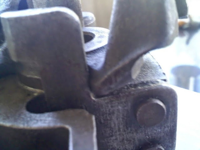
With the carrier now contacting the retractor, the flexing seat opening allows pop out. See this 1954-1971 carrier is beefier at seat. This works fine for all but the ham-fisted. Ham fisters are the meat and potatoes of the HD clientele.
Even though a workable system was in place, the education needed was not. A “ham fist proof” system was needed to stop the pop out.
In 1966 it was instituted. It was comprised of 3 items.
(two being unknown to all but the most ardent students of these bikes. The last is still being totally misunderstood).
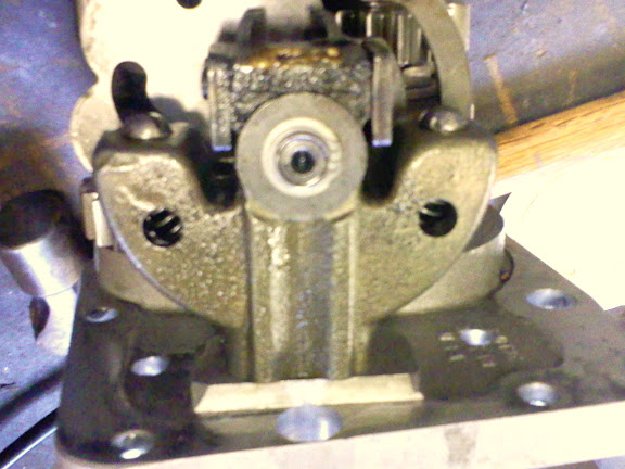
- The retractors themselves got beefed so they didn't flex and allowing the carrier seat to over-rotate. Over rotation will allow ball to come free from seat. The 3 pics above show a 1966-1971 tower and the beefy retractors. I do not have any pics of the 65< retractors right now.
- A .015“ thick shim that slipped over the shift shaft before it gets installed into the c'case. What this did was to get ball deeper in seat. If you knew that stuff, move to the head of the class and see if you know about item 3.
- The tower shim that goes between tower and door. If you think that was instituted as a gear spacing tool move back to the rear of the class. It was the mate to the shaft shim. The shim is a shifting improvement tool, as it also helped deepen the ball engagement.
These changes made popped out balls a non issue and as a side effect of the new geometry, the shift throw at peg got shorter. But like many mechanical mods, they created a new problem. That is problem 'B' from above.
(B) break ball clean off.
All this deeper ball engagement allowed the stem under the ball to get pinched in the seat opening.
This “pinch” shows on the stem as a little worn area or a dent like in the pic below.
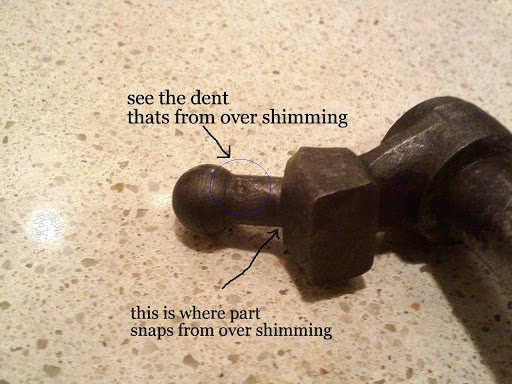
To stop the new problem, the shaft shim was dropped, leaving just the tower shim. In 1973, the new wrought steel shaft head and ball addressed all the shims, so the shims were dropped. The amf wrought head was pinned to the shaft. Those pins broke or fell out. These need the head and shaft to be welded solid.
A 1966-1971 tower with the original HARDENED retractors.
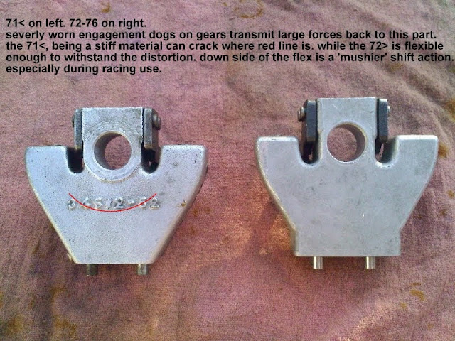
A tower out of any 1975-up with the soft retractors.
Keywords: bent, distorted, worn. In plain English, the retractors went to hell.
Question:
- buskit: Are hardened retractors available? Did they have a different part# or just a production change? I ask because I have two sets, one aftermarket junk that's modified to work and is in use. And one set that is obviously not hardened as they are bent. I'd like a set to put on my new tower when I re-set up my shifter. It works fine. But I don't want the aftermarket tower to stay.
- Dr Dick: That's actually what started this thread - questions by mtc496 on how to correctly fit a trock tower.
The trock tower is a pretty raw item as delivered. There is massaging required if you want it be as good as it can be.
To get it there, you need to understand the factory stuff inside and out. That particular info is what we cover next. There are no shortcuts to blueprinting. That's why most guys don't undertake it. Out of the box the trock tower may be worse than the factory units. When blueprinted, it's way better than anything else.
What you need is a 1966-1971 tower to salvage the retractors from. On 77-up, you can use the 65< units also. 77> don't have as much peg throw as 76< did. The long peg throw of the earlier bikes applies more leverage to the carrier stops.
They need the 66> where the 77> bikes work fine with either. Finding cracked towers at an indy will get you what you need for cheap. You're lookin for the tower on the left. They crack at the red line.
Questions:
- doodah man: Is setting the “retractor” arm pins a straight forward installation? or is there some trickery to it
- Dr Dick: In order to replace the arms you grind/drill off the rivet heads, then drive the arms off. This leaves the rivet shanks in the tower. The shanks are a press fit into tower. That's important.
So, you need new rivets with good tight fit to tower and to arms. If there is any sloppy rivet diameters, the arms will move in operation. Finding a good used tower with hard arms is usually a better option than transplanting them. - buskit: Does my trock tower use rivets? Or are they “built in”? Meaning you pean over the nubs cast into the piece?
- Dr Dick: The rivets are actually precision pins that you peen both ends. There is no rivet head. Rivet was a terrible choice of word on my part. These pins are already installed in the trock tower.
Here is the 1977-1985 tower. Changed for clearance of the 1977 up shifter shaft that came in from the left.
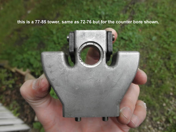
And here is the old trock cast iron tower, by far the best shift fork control and never breaks. Best of both worlds.
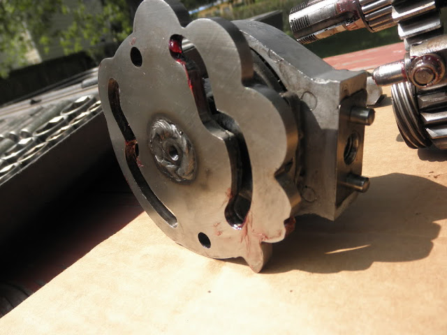
Shift Shaft
To this point, we have talked about each part (with the exception of the centering springs and the tower) and how it interacts with its mates. It's time to carry this a bit farther from the workbench.
At this point, you should have a working knowledge of how your toe moves the forks. Every part we talked about so far is hung from the trans door, except one. The shift shaft. That part is hung from the engine cases.
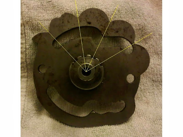
So, you need to test the shift shaft interface with the carrier.
One is located by the case (shift shaft) and one is located by door and tower (pawl carrier).
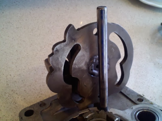
Procedure:
- Take your empty tower, (leave centering springs and pawls on work bench. You don't want them yet) and install the carrier and cam plate. Drop on washer and snap ring. What you have is a tower assm less the centering springs and pawls and pawl springs. Check for excessive slop at axle. How? Assm tower to door/fork shaft assm (see above for door/shaft assm) make sure plunger and spring are installed in door. Tighten tower to door. How parallel is cam plate to fork shaft?
As parallel goes away, the hats lose operational integrity to camplate slots. The 3-4 hat can bind on the brim and the 1-2 will lose slot engagement depth.
How much is too much? That is subjective - how much tire or chain wear is too much? You need to used your judgement to decide if your Ok or if you need to work on plate/fork shaft parallelism. Observe and deduce. (below, the cam plate is rotated into a non operational position, but this pic should show you the parallel im talking about)

- Install door sub assm to case to check carrier operation.
- Plunger pressure should allow you to center the carrier in its travel and hold it there.
- Slip shift shaft in case.
- Assm door to case and tighten.
- On 1977> install primary cover. On 76< install cam cover.
At this point any rotation of shift shaft will translate into carrier (not camplate) rotation. Does the carrier/shift shaft interface operate like silk thru the entire stroke? It should. If not find out why. For instance:- Bent shafts
- Overly tall welds on beefed 73> style shaft heads that results in a pinched situation between tower top and welded shaft.
- Over shimmed tower/shaft resulting in pinch interference at nest. (See above)
Next, we tackle carrier centering, pawling bias, and cam plate slot registration.
Question:
- megavites: What tranny issue might cause the shift arm to occasionally spin the shaft without actually clicking into the next gear. It also occasionally binds. I'm pretty sure the shifter is not spinning on the shaft and I'm wondering if this is an easy fix or leading me down the road to a tranny overhaul on my 73 XLCH.
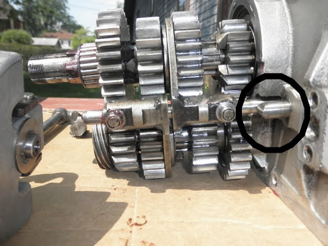
- Dr Dick: I'll bet you have the most common shifter problem. Go to 1st post and see item 1). See that pin (used on 73>)? I'll bet yours is sheared. As a cure guys will weld the head to the shaft (I do it) and the weld will break if the weld isn't prepped well. I'll bet one of those two scenarios is at hand for you.